4 calibration where detector is a replacement part, 5 troubleshooting – Fluke Biomedical 943-25 User Manual
Page 15
Maintenance, Calibration, and Troubleshooting
Calibration Where Detector Is a Replacement Part
4
4-3
4.4 Calibration Where Detector Is a Replacement Part
Calibration of a replacement detector unit depends on the uniformity of response of the detector. The
replacement detector should have the same size scintillation disc as the original detector in the system.
The detector should be connected to the readout with all the cable that will be in place during normal
operation since the high voltage setting is slightly cable dependent. At the readout, set the discriminator
level to the level indicated on the data sheet (normally 0.2 VDC).
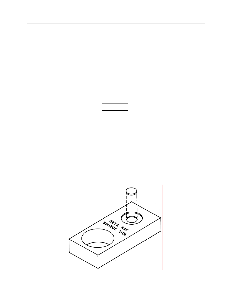
1. Insert the detector into the cavity provided in the standard geometry.
2. Place
the
9O
Sr button source, blank side up (P/N 844-36-14), on the slide in the standard geometry
(Figure 4-1).
3. The expected count rate for the button source should be determined. It is recorded on the
calibration data sheet. Correction must be made for decay. (The half-life of the source is 29.12
years.)
4. Adjust the high voltage power supply to the detector so that the net count rate corresponds to the
expected count rate calculated in Step 3.
The net count rate is the indicated count rate minus
the background count rate.
5. The count rate will increase and decrease in conjunction with power supply voltage. If the high
voltage reaches 2000 VDC without achieving the necessary count rate, suspect a defect in the
detector, wiring, or readout device.
6. If more than one button source is available, measure all the button sources. The lowest activity
source should be used first. Record the high voltage values that reproduce the original count rates.
Average the high voltages to determine the best value for all the button sources.
4.5 Troubleshooting
Troubleshooting is indicated for the detector when the measured output of the check source or some
other beta source shows a marked change in the count rate observed at the readout while high voltage
has remained
constant.
NOTE
Figure 4-1. Standard Geometry Drawer Inverted to Show Recess for Beta Disk Sources