Wiring instructions – GAI-Tronics 13314-003 Horn Drivers (30-Watt) User Manual
Page 2
Pub. 42004-096D
Model 13314-003 Div. 2 Hazardous Area 70 Volt Horn Driver
Page:
2 of 4
f:\standard ioms - current release\42004 instr. manuals\42004-096d.doc
05/11
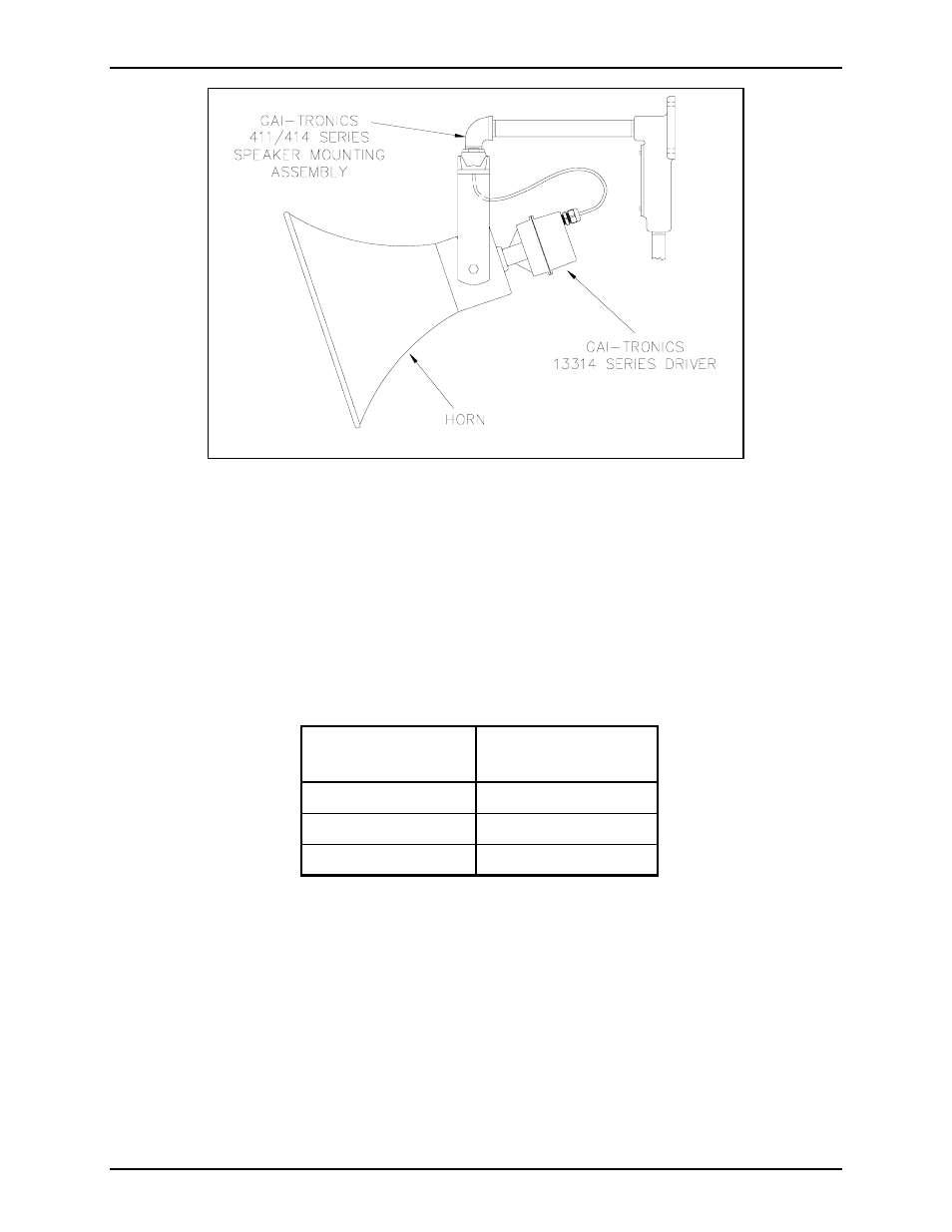
Figure 2. Typical Installation
The installation of this speaker assembly must conform to regulations governing electrical equipment for
hazardous locations and provisions of the National Electrical Code.
Install the mounting assembly and the horn, then complete the following instructions to install the driver
onto the horn.
Wiring Instructions
Refer to the following chart to determine the appropriate gauge speaker cable.
Cable
Options
Distance of Cable
Run in Feet
No. 18 AWG
6,250
No. 16 AWG
9,900
No. 14 AWG
15,800
Field wiring to the driver must be made using the attached three-conductor type SO cord. Connect these
wires as follows:
• Green: earth ground
• Black: amplifier 70V + terminal
• White: amplifier 70V − (com) terminal
The horn driver is factory-connected for 30-watt tap setting. If no wattage tap changes are required,
screw the driver assembly onto the rear of the horn as shown in Figure 2.