Changing the wattage tap setting – GAI-Tronics 13314-003 Horn Drivers (30-Watt) User Manual
Page 3
Pub. 42004-096D
Model 13314-003 Div. 2 Hazardous Area 70 Volt Horn Driver
Page:
3 of 4
f:\standard ioms - current release\42004 instr. manuals\42004-096d.doc
05/11
Changing the Wattage Tap Setting
1. If another wattage tap setting is desired, it is recommended that the driver assembly be disconnected
and removed from the horn for convenience of changing taps.
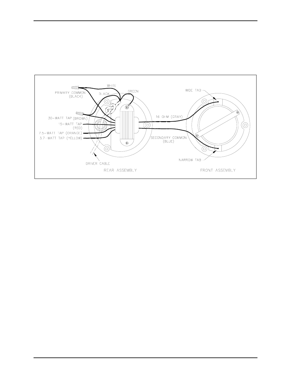
2. Remove the three Phillips screws that hold the driver together, and pull the rear assembly away from
the front assembly. See Figure 3. Use care to avoid damaging the gasket.
Figure 3. Driver Outline Diagram
3. Unscrew the wire nut from the driver transformer’s brown wire that is joined to the driver cable’s
(SO cable) black wire. Terminate the brown wire with a nut or approved connector to avoid shorting
out.
4. Select the desired wattage tap wire, as shown in Figure 3.
5. Strip the wire back approximately 3/8 inch. Connect the desired wattage tap wire to the driver
cable’s black wire using a wire nut or approved connector.
6. It is not recommended that these wires be cut in case of future changes. Carefully push all primary
transformer wires into the space in the rear section of the enclosure.
7. After ensuring that the gasket is properly seated on the front assembly, align the rear assembly holes
with the front assembly holes and re-install the three screws.
8. Re-install the driver assembly to the horn and reconnect the cable to the field connection.