GAI-Tronics 234 Stanchion Assembly User Manual
Page 8
Pub. 42004-194M
234 Stanchion Assembly and Model 234SBA Stanchion Broadcast Assembly
Page 8 of 11
f:\standard ioms - current release\42004 instr. manuals\42004-194m.doc
11/12
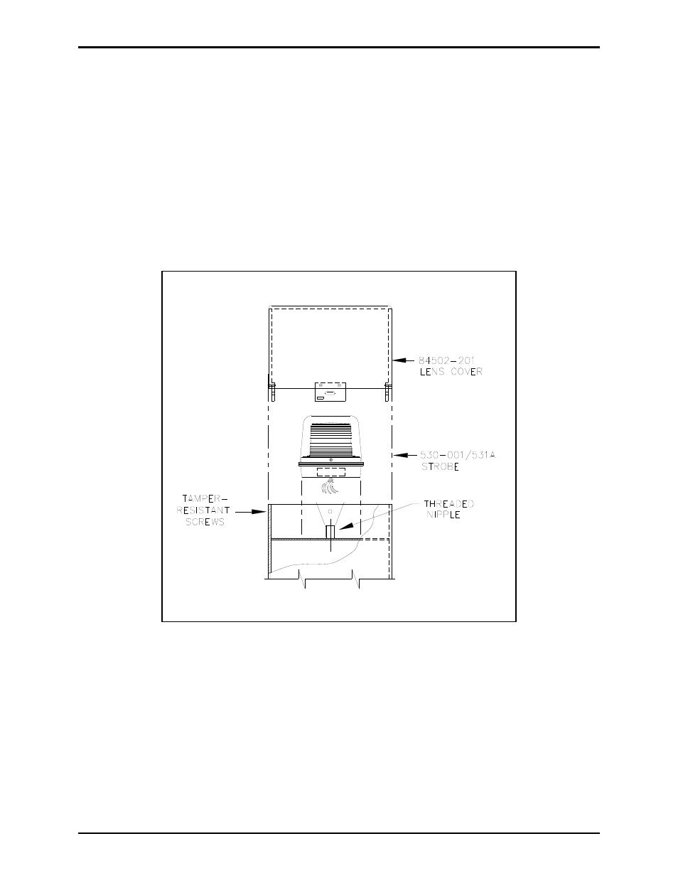
Model 530-001 or 531A Strobe and 84502-201 Lens Cover Installation
1. Insert the strobe’s seven 15-foot wires through the stanchion’s threaded nipple, and allow the wires to
extend to the base of the stanchion. See Figure 8.
2. Screw the strobe onto the threaded nipple. Secure the Model 84502-201 Lens Cover with four
security screws.
3. Apply a small amount of clear RTV silicone sealant or equivalent to each screw thread to reduce the
possibility of rust forming in the screw threads.
4. Separate the orange and violet wires necessary for the telephone connection, and extend those wires
through the stanchion cutout for the telephone.
Figure 8. Strobe Assembly