Wiring – GAI-Tronics 473-002 Centra-Page Outdoor Wall Station User Manual
Page 4
Pub. 42004-214C
Model 473-002 Centra-Page Outdoor Wall Station
Page: 4 of 7
\\s_eng\gtcproddocs\standard ioms - current release\42004 instr. manuals\42004-214c.doc
08/05
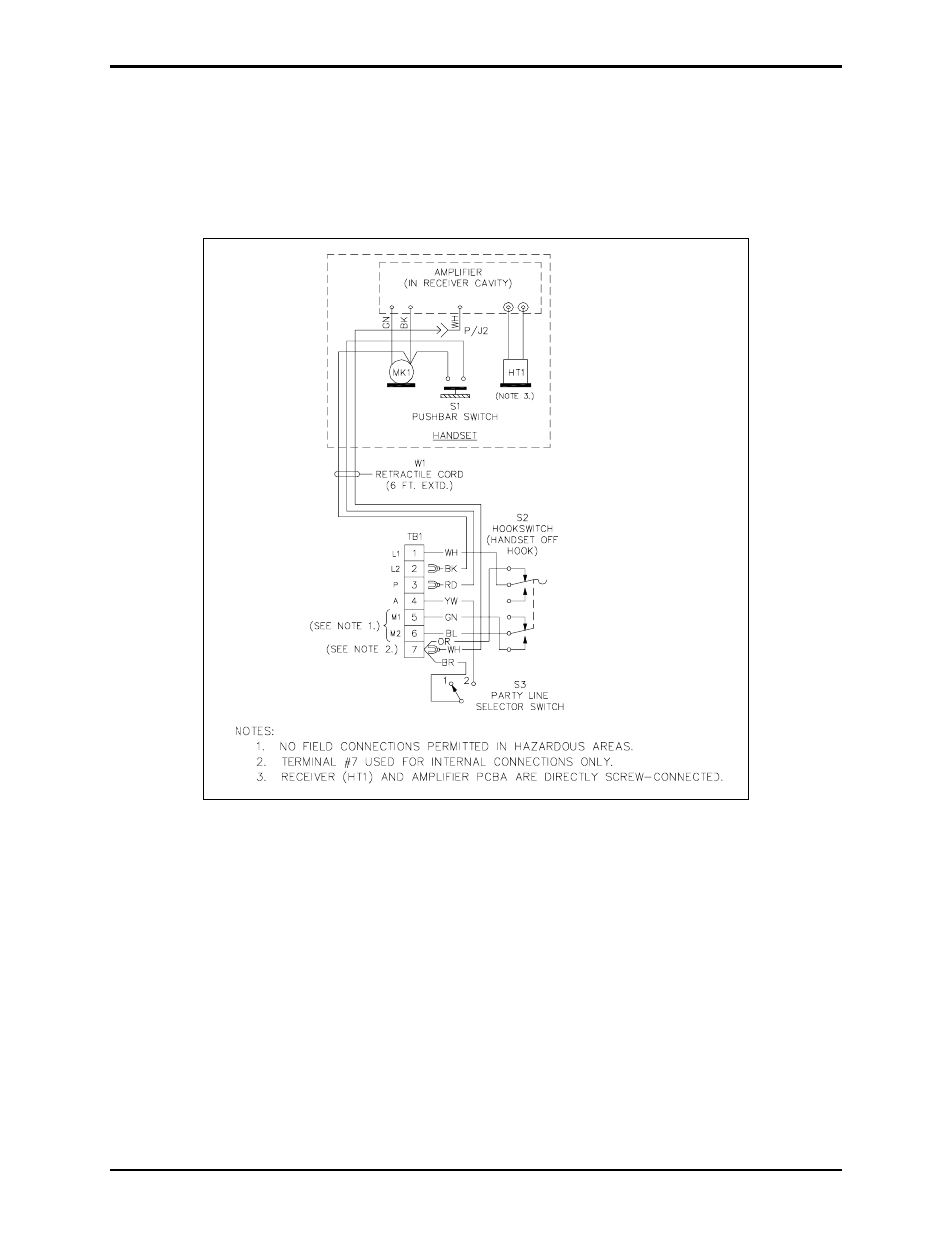
Wiring
The configuration of the cable entering the Model 473-002 depends on the chosen wiring method. Refer
to Pub. 42004-356, Centra-Page Control Drawing No. 72979, and Pub. 42004-222, Model 10468-002
Centra-Page Central Cabinet for additional information. Refer to Figure 2 below for the wiring
terminations inside the Model 473-002 Outdoor Station.
Terminations L1, L2, P, and A correspond to identical terminations at the card rack assembly. These four
connections must be complete as two pair. The first pair, L1 and L2, serves as both the communications
path and the power supply. The second (control) pair provides party line selection or page line activation.
Terminations M1 and M2 are not used in typical installation. The speaker conductors are connected
directly to the associated speaker or driver.
Installing the Model 473-002 in a Division 1 area requires that the four station conductors terminate in a
safety barrier (Model 10439-102) prior to entering the Division 1 area. This configuration creates
intrinsically safe wiring to the station. Speaker wiring may not pass through the station. Refer to Pub.
42004-356, Control Drawing 72979, for proper installation.
The wiring distance limitation for a handset station is specified as 10,000 feet without a hazardous area
safety barrier, and 3,000 feet with a barrier. This distance is determined by degradation from cable
capacitance more than cable resistance. The use of heavier wire will not fully compensate for a greater
distance.
Figure 2. Station Internal Wiring Details