GAI-Tronics WCB104 Wireless Call-Box Installation Guide User Manual
Page 9
Pub. 42004-327A
Model WCB104 Wireless Call Box Installation Guide
Page: 9 of 10
\\s_eng\gtcproddocs\standard ioms - current release\42004 instr. manuals\42004-327a.doc
12/00
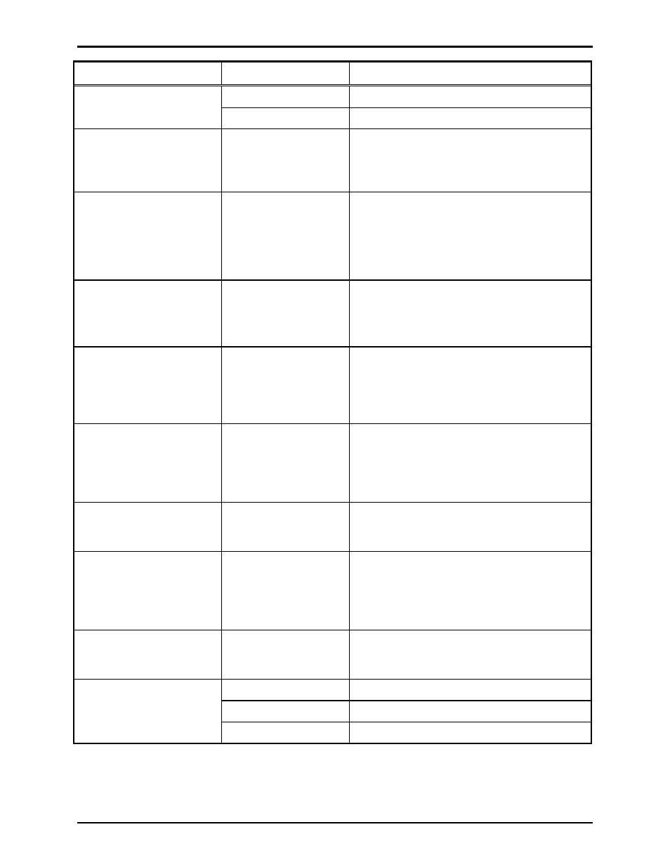
Problem Reason
Solution
1. Other
Depress Reset button S2.
No microphone audio.
2. Handset failure
Replace the handset with a known good unit.
Ringing, but C
ALL
P
LACED
LED does not flash.
C
ALL
P
LACED
LED
failure
During ringing, the C
ALL
P
LACED
LED should
measure:
TB1-3 and TB1-4 = 1.7 V dc
Replace LED lamp assembly if failed.
C
ALL
P
LACED
LED flashes,
but does not turn on
steadily.
Unable to establish
communication with
the cellular network.
1. Place handset back on hook and try to
establish call again.
2. Depress Reset button S2.
3. Check antenna connections.
4. Replace cellular module with a known
good unit.
C
ALL
C
ONNECTED
LED
doesn’t light when operator
answers.
C
ALL
A
NSWERED
LED
failure
Once the operator speaks, the C
ALL
A
NSWERED
LED should measure:
TB1-5 and TB1-6 = 1.7 V dc
Replace LED lamp assembly if failed.
Receiver volume does not
increase.
Push button failure
Check operation of the push button. The push
button should measure:
Incoming Call = 11.0 V dc or greater during
(2s - ON, 4s – OFF)
Replace push button if failed.
Ringer does not sound.
Ringer failure
Check operation of the ringer. The ringer
should measure:
• Active = 1.0 ohm or less
• Inactive = infinite
Replace ringer if failed.
Solar Panel Integrity Loop
Failure reported, but
integrity loop is intact.
Integrity Loop failure
Check operation continuity of the loop. The
loop should measure 1.0 ohm or less.
Re-terminate connector if necessary.
Unit does not call-in when
tilted.
Tilt Sensor failure
Check operation of the tilt sensor. The sensor
should measure:
• Inactive = 1.0 ohm or less
• Active = infinite
Replace sensor if failed.
Handset Integrity Loop
failure reported, but
integrity loop is intact.
Integrity Loop failure
Check operation continuity of the loop. The
loop should measure 1.0 ohm or less.
Re-terminate connector if necessary.
1. Power failure
Check power to the unit.
2. Call-in failure
Depress Call-in switch.
Unit does not call-in.
3. Other
Depress Reset button S2.