Installation, Wiring – GAI-Tronics 12584-001 I/O Control Module (for AMI) User Manual
Page 2
Pub. 42004-359B
Model 12584-001 I/O Control Module
Page: 2 of 7
\\s_eng\gtcproddocs\standard ioms - current release\42004 instr. manuals\42004-359b.doc
10/08
Installation
Wiring
WARNING
Do not apply power until all the connections have been wired.
WARNING
Connect only to a UL-listed Class 2 power source.
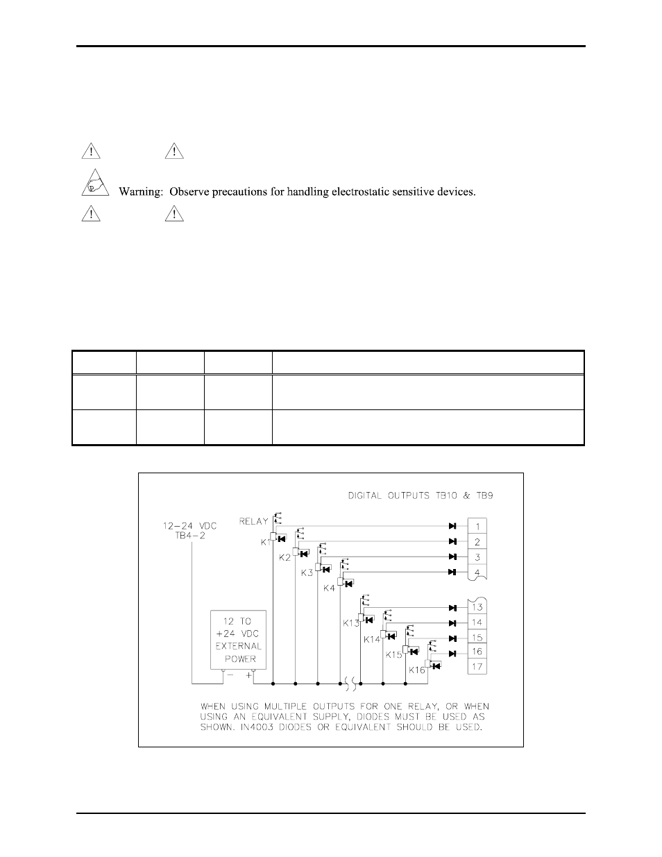
TB10 and TB9 - Digital Output Connections
The TB10 and TB9 connectors each provide 16 digital (common ground) output connections designed to
drive externally-mounted relays or other indicating circuits. Each output can sink up to 150 mA of the
current. External circuitry (relays, indicators, etc.) must be powered from an external power supply of the
same voltage used to power the I/O Control Module (12 to 24 V dc). The ground (or dc common)
terminals of the external power supply must be tied to TB4-2.
Terminal Labeled Function Type
TB10-1 to
TB10-16
O
UT
-1
TO
16
Digital
output
Idle = +V dc, active (low) = sink100 mA maximum
TB9-1 to
TB9-16
O
UT
-17
TO
32
Digital
output
Idle = +V dc, active (low) = sink100 mA maximum
Figure 2. Typical digital output relay wiring