GAI-Tronics 12584-001 I/O Control Module (for AMI) User Manual
Page 6
Pub. 42004-359B
Model 12584-001 I/O Control Module
Page: 6 of 7
\\s_eng\gtcproddocs\standard ioms - current release\42004 instr. manuals\42004-359b.doc
10/08
TB8 Terminal Block Assignments
Terminal Labeled Function
Type
TB8-1
I
N
-25
Input 25
Activates input #25
TB8-3
I
N
-26
Input 26
Activates input #26
TB8-5
I
N
-27
Input 27
Activates input #27
TB8-7
I
N
-28
Input 28
Activates input #28
TB8-9
I
N
-29
Input 29
Activates input #29
TB8-11
I
N
-30
Input 30
Activates input #30
TB8-13
I
N
-31
Input 31
Activates input #31
TB8-15
I
N
-32
Input 32
Activates input #32
TB8-2, 4,
6, 8, 10,
12, 14, 16
GND
Ground Ground
reference
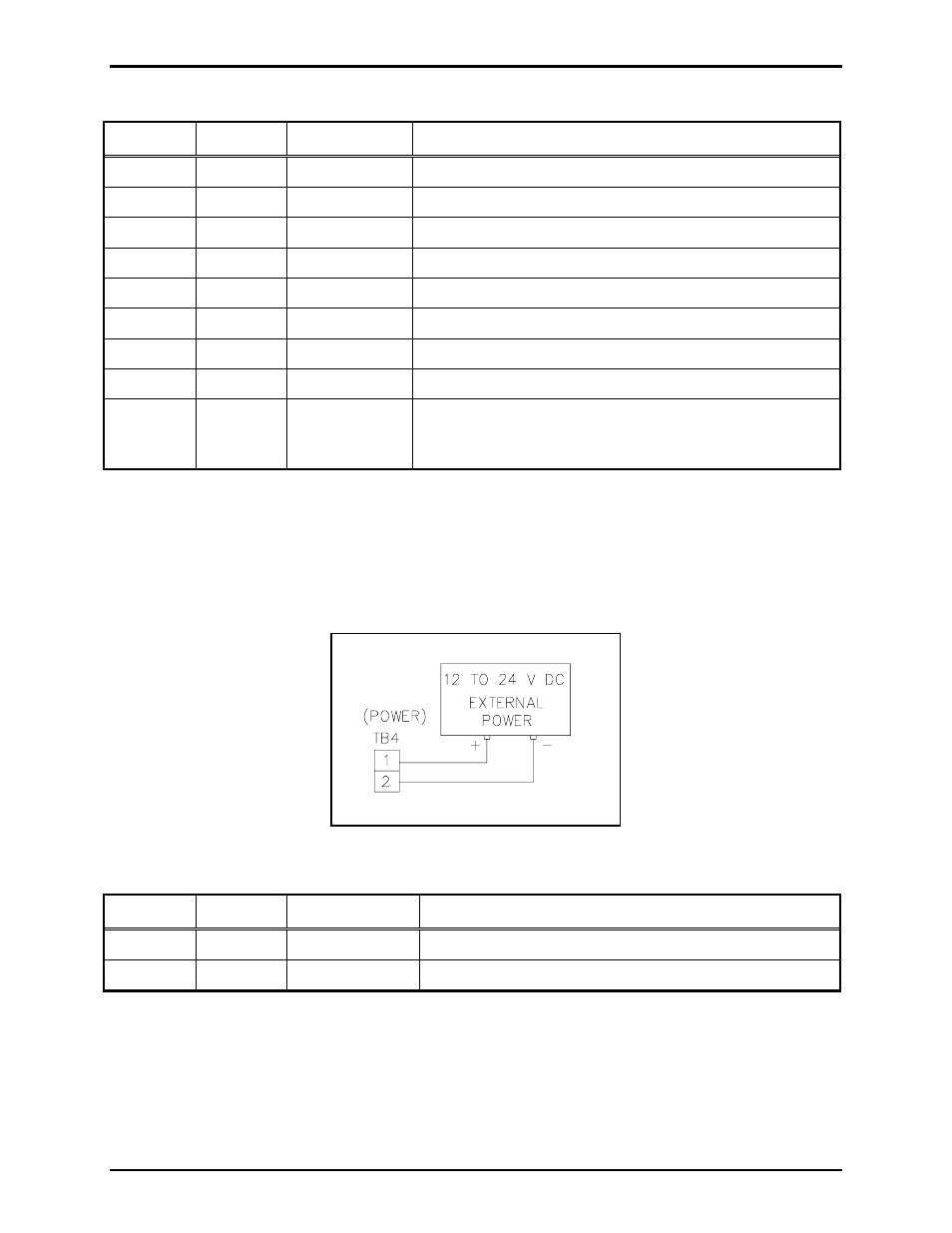
TB4- Power Connections
The I/O Control Module requires a dc power supply. The dc power supply voltage must be between 12
and 24 V dc. TB4 is used for power connections. Please refer to the TB4 terminal block assignment
chart and Figure 5 below.
Figure 5. Power connections at TB4
Terminal Labeled Description Function
TB4-1
+
Power (+)
12 to 24 V dc power supply positive terminal
TB4-2
-
Power (-)
12 to 24 V dc power supply negative terminal