Setup, Preparation – GAI-Tronics 10960-001 Zone Interface Module (ZIM) User Manual
Page 7
Pub. 42004-369B
10960 Series Zone Module Interface
Page: 7 of 10
\\s_eng\gtcproddocs\standard ioms - current release\42004 instr. manuals\42004-369b.doc
08/05
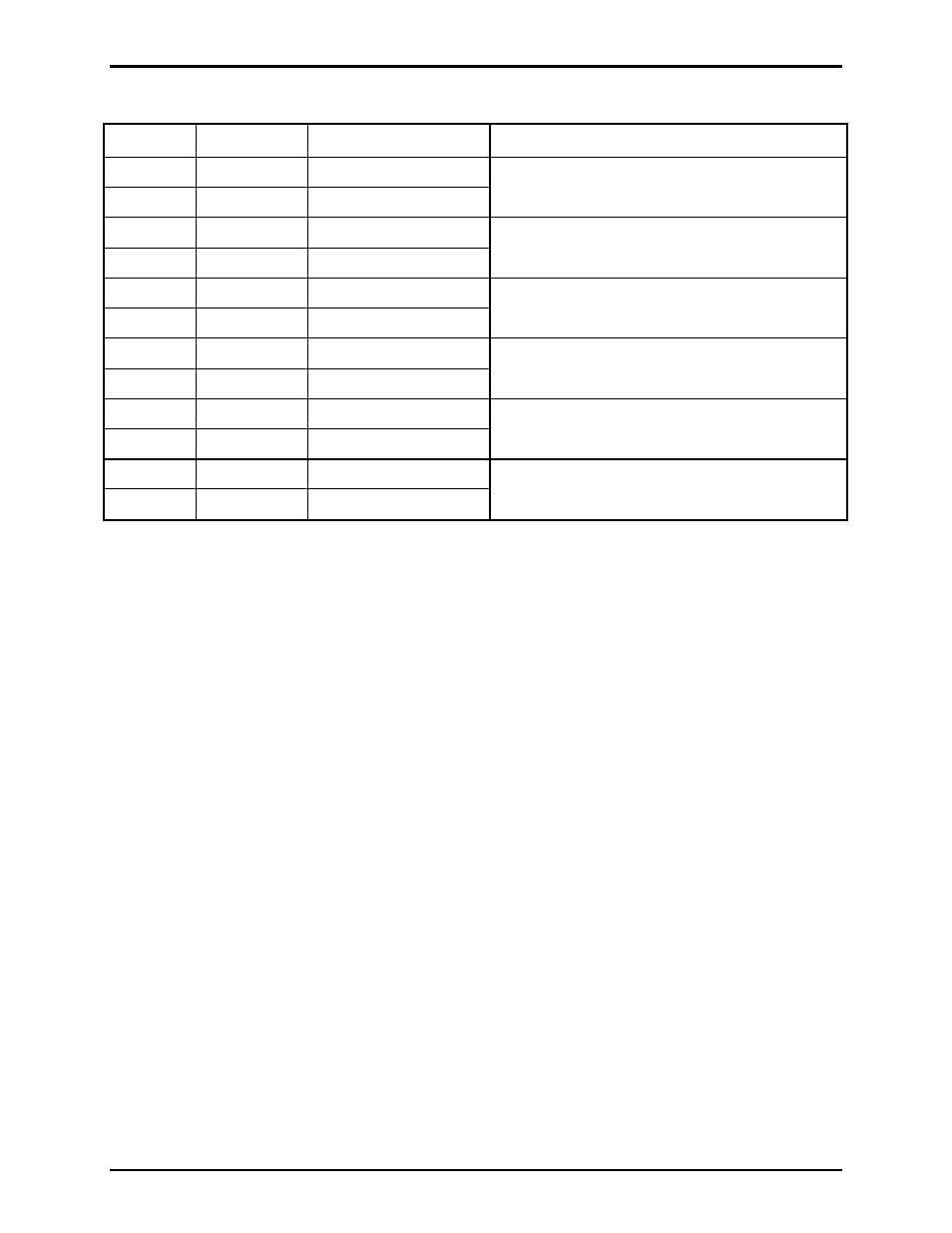
Page/Party
®
System
Terminal Labeled
Description
Function
1
PG
(L1)
Page (L1)
2
PG
(L2)
Page (L2)
Connects to the page line of Page/Party
®
system
3
PTY1
(L1)
Party 1 (L1)
4
PTY1
(L2)
Party 1 (L2)
Connects to the party 1 line of Page/Party
®
system
5
PTY2
(L1)
Party 2 L1)
6
PTY2
(L2)
Party 2 (L2)
Connects to the party 2 line of Page/Party
®
system
7
PTY3
(L1)
Party 3 (L1)
8
PTY3
(L2)
Party 3 (L2)
Connects to the party 3 line of Page/Party
®
system
9
PTY4
(L1)
Party 4 (L1)
10
PTY4
(L2)
Party 4 (L2)
Connects to the party 4 line of Page/Party
®
system
11
PTY5
(L1)
Party 5 (L1)
12
PTY5
(L2)
Party 5 (L2)
Connects to the party 5 line of Page/Party
®
system
Setup
Preparation
When the unit is ready for testing, please ensure the ZIM is installed and connections are made consistent
with the Wiring section on page 4. Please verify the following:
• DC power connected and polarity is correct
• Inputs are connected
• Outputs are connected
• Phone line is connected (if applicable)
• Page and party lines are connected (if applicable)
• Paging amplifier is connected (if using 600-ohm output)
• Resistive line balance is installed to support the Page line.
• Existing party line resistive line balancing is disconnected.