GAI-Tronics 7085-004-UL, 7085-004-EX SmartSeries Multi-Party Hazardous Area Handset/Speaker Amplifier Enclosure w/ Alternate Page User Manual
Page 4
Pub. 42004-694L2B
Model 7085-004-UL/EX SmartSeries Multi-Party Haz. Area Amplifier Enclosures
Page:
4 of 12
\\s_eng\gtcproddocs\standard ioms - current release\42004 instr. manuals\42004-694l2b.doc
11/07
Internal
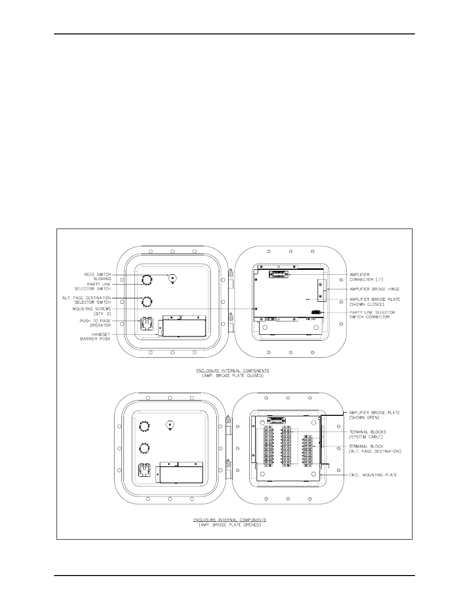
The multi-party enclosures contain three terminal blocks, an interior mounting plate, an amplifier bridging
plate, and a connector for the mating Model 709-901 Amplifier. The amplifier bridging plate is hinged on
one side and attached on the opposite side with two #10-32 screws. For system cable installation, the
screws to this plate must be removed and the bridging plate swung open 90º. Upon installation of the
wiring cable, the amplifier bridging plate can be rotated closed and reattached with the two #10-32 screws.
This plate will then serve as a protection for the amplifier and the switches from the system cable when the
unit is completely closed. Refer to Figure 3.
The alternate page destination selector switch is connected through an additional 8-point terminal block,
with wiring directly to the front door. The 8-point terminal block is located on the right side of the internal
mounting plate. See Figure 3.
The party line selector switch can be disconnected from the amplifier bridging plate by means of the 12-pin
connector. Upon installation of system cable, after the amplifier bridging plate has been reattached, plug
the 12-pin connector back into its receptacle.
N
OTE
: The front door can be swung approximately 120º before the plug must be disconnected.
Figure 3. Model 7085-004-UL/EX Amplifier Enclosures - interior view
- 7085-004-EX-F07049 SmartSeries Multi-Party Hazardous Area Amplifier Enclosure with Alternate Page 7085-001-UL, 7085-001-EX SmartSeries Multi-Party Hazardous Area Handset/Speaker Amplifier Enclosure 708-001-UL, 708-001-EX SmartSeries Single Party Hazardous Area Handset/Speaker Amplifier Enclosure 708-001-EX-F07048 SmartSeries Single Party Hazardous Area Amplifier Enclosure 707-001-UL, 707-001-EX SmartSeries Hazardous Area Speaker Amplifier Enclosure 7085-005-UL, 7085-005-EX SmartSeries Multi-Party Hazardous Area Handset/Speaker Amplifier Enclosure w/ RTU Control 7085-001-EX-F07044 SmartSeries Multi-Party Hazardous Area Amplifier Enclosure 707-001-EX-F07045 SmartSeries Hazardous Area Speaker Amplifier Enclosure