GAI-Tronics ICS Hazardous Area Page/Party Stations User Manual
Ics hazardous area page/party, Station quick installation guide, Installation
Pub. 42004-723L2GQG
GAI-Tronics Corporation 400 E. Wyomissing Ave. Mohnton, PA 19540 USA
610-777-1374
800-492-1212 Fax: 610-796-5954
V
ISIT WWW
.
GAI
-
TRONICS
.
COM FOR PRODUCT LITERATURE AND MANUALS
G A I - T R O N I C S ® C O R P O R A T I O N
A H U B B E L L C O M P A N Y
ICS Hazardous Area Page/Party
®
Station Quick Installation Guide
Important Safety Instructions
1.
Read, follow, and retain instructions – All safety and operating instructions should be read and followed before operating the unit. Retain instructions for future
reference.
2.
Heed warnings – Adhere to all warnings on the unit and in the operating instructions.
3.
Attachments – Attachments not recommended by the product manufacturer should not be used, as they may cause hazards.
4.
Servicing – Do not attempt to service this unit by yourself. Opening or removing covers may expose you to dangerous voltage or other hazards. Refer all
servicing to qualified service personnel.
5.
This permanently connected apparatus must have a UL Listed 15-amp circuit breaker incorporated in the electrical installation of the building.
USA and Canada Consult the National Electrical Code (NFPA 70), Canadian Standards Association (CSA 22.1), and local codes for specific requirements regarding
your installation. Class 2 circuit wiring must be performed in accordance with NEC 725.55.
WARNING
In 24 V dc systems: Under NO condition should this equipment be operated from a battery charger without the batteries connected.
In 24 V dc systems, most chargers have an unloaded output of 35 to 45 volts that can quickly damage the equipment designed for nominal 24 volts. The maximum
battery voltage should never exceed the maximum specified input voltage.
Installation
These enclosures must be installed by trained, qualified and competent personnel. Installation must comply with state and national regulations, as well as safety
practices for this type of equipment.
WARNING
Do not install this equipment in hazardous areas other than those indicated on the approval listing in the “Specifications” section. Such
installation may cause a safety hazard and consequent injury or property damage.
The mounting location must be flat and provide proper clearance, rigidity and strength to support the enclosure and all contained devices. The enclosures are equipped
with factory-installed hinges. The enclosures should be mounted with hinges on the left.
WARNING
Do not mount the enclosure with hinges on the top or bottom side.
Securely fasten the enclosure to the mounting location, using 3/8-inch (10mm) diameter steel mounting bolts and washers, or washer head bolts.
WARNING
Do not disconnect equipment while energized.
Insure proper grounding to protective earthing.
Inspect and clean the machined flange flame joint surfaces of both the cover and box. Surfaces must be smooth, free of nicks, scratches, dirt or any foreign particle
build-up that would prevent a proper seal. Surfaces must seat fully against each other to provide a proper explosion-proof joint. Clean surfaces by wiping with a clean
lint-free cloth.
Apply a light coat of Killark “LUBG” lubricant to flange surfaces and close the cover. Install and tighten all cover bolts to 30 ft.-lbs. Make certain no cover bolts are
omitted. Use only those bolts supplied with the enclosure.
When installing an add-on station, consult the appropriate system layout diagrams. These figures, when used in conjunction with the station installation information
and cable layout guide, should provide all the information necessary to install additional Page/Party
stations.
General Information and Available Options
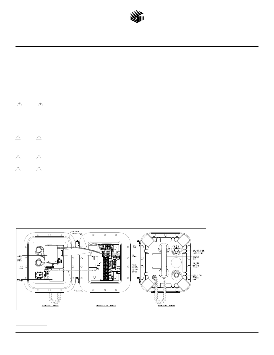
This guide covers the installation of the ICS Hazardous Area Page/Party
®
Station. Figure 1 shows configurations with the following options:
Universal ac or 24 V dc
power
Single or multi-party system
Amplifier only
SmartSeries
Alternate page destination
Emergency party line (EPL)
VLC
RTU
All Call
All ICS Stations are wired in parallel. Good system layout design minimizes the cable required. Refer to Pub. 42004-723L2 at the “Manuals & Specs” link at
www.gai-tronics.com
for detailed explanations of the available configuration options and adjustments, and system design information.
Figure 1. ICS Station with available options (AC Version shown)