Mounting the enclosure, Cable entries, Available adjustments – GAI-Tronics ICS Hazardous Area Page/Party Stations User Manual
Page 2: Approvals
Pub. 42004-723L2GQG
ICS Hazardous Area Page/Party
®
Station Quick Installation Guide
Page 2 of 2
f:\standard ioms - current release\42004-xxxxqg quick guides\42004-723l2gqg.doc
11/14
Mounting the Enclosure
N
OTE
: The mounting surface must be able to support the weight of the 50-lb. aluminum station.
The enclosure must be securely fastened with 3/8-inch (10mm) diameter steel mounting bolts located on all four mounting feet. Refer to
Figure 2
. Stainless steel
hardware is recommended in outdoor applications.
N
OTE
: Refer to the Killark Installation, Operation, and Maintenance Data Sheet enclosed with the unit for additional information.
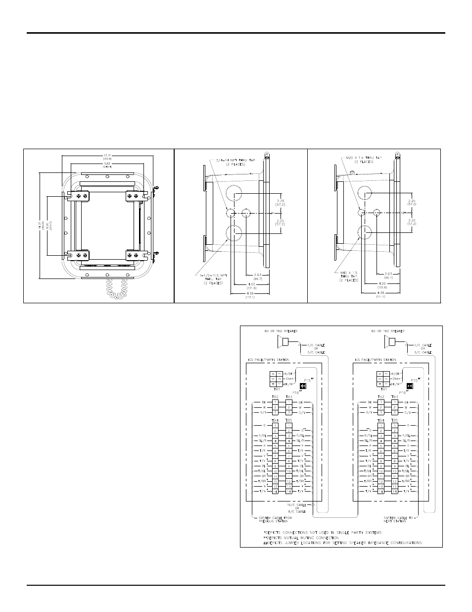
Cable Entries
Refer to
Figure 3
for the standard NPT conduit entries, and
Figure 4
for the standard metric cable gland entries. Ensure any unused openings are sealed with proper
fittings per local standards. All metric cable entry devices and blanking elements shall be certified in type of explosion protection flameproof enclosure “d” with an
IP66 rating, suitable for conditions of use and correctly installed. Any conduit NPT plugs (blanking elements) must be explosion-proof with a Type 4X rating. Use
field wiring suitable for the ambient temperature. Basic wiring connections are shown in Figure 5. Use GAI-Tronics 60029 series multi-party cable or 60038 single
party cable terminated with #6 spade lugs. Torque the terminal block screws to 8–10 in-lbs. (0.90–1.13 n-m) when attaching the spade lugs.
Figure 2. Mounting Details – Rear View
Figure 3. Standard NPT Conduit Entries – Bottom View
Figure 4. Standard Metric Cable Entries – Bottom View
Available Adjustments
Most optional equipment is preconfigured to a default standard at the factory. The
following is a partial list of the available adjustments and settings that may be
needed:
Approvals
NRTL listed ..................... Hazardous locations Class I, Div. 1, Groups B, C & D;
(USA and Canada) ........................................... Class II, Div. 1, Groups F & G;
Class III, Div. 1
T6, Type 4X
CE Mark
Certificate No.
Notified Body Id No. 0539
UL International DEMKO A/S
Lyskear 8
DK-2730 Herlev
Denmark
DEMKO 09 ATEX 0909372 (ATEX) ...................... II 2 G Ex d [ib] IIB + H2 T6
IECEx UL 09.0009 (IECEx) ..................................... II 2 G Ex d [ib] IIB + H2 T6
Figure 5. Typical installation wiring configuration
N
OTE
:
Station input power can be through system cable or through a separate power source
cable. See Pub. 42004-723L2 for the possible beacon, RTU activation, and speaker
impedance configurations.
Main PCBA
VLC Option
SmartSeries Option
Speaker Volume
Speaker Volume
FSK Transmit Level
Receiver Volume
VLC Override
Address
Transmit Level
Test Tone
Mutual Muting
Page Control
Termination PCBA
Remote Signaling
Speaker impedance