Field wiring, Data (tx/rx), Power – GAI-Tronics 12576-50315 Desktop Access Panel with LCD Display User Manual
Page 4: Ground
Pub. 42004-733L2C
Model 12576-503 & 12576-50315 Desktop Access Panels with LCD Display
Page 4 of 13
e:\standard ioms - current release\42004 instr. manuals\42004-733l2c.doc
07/14
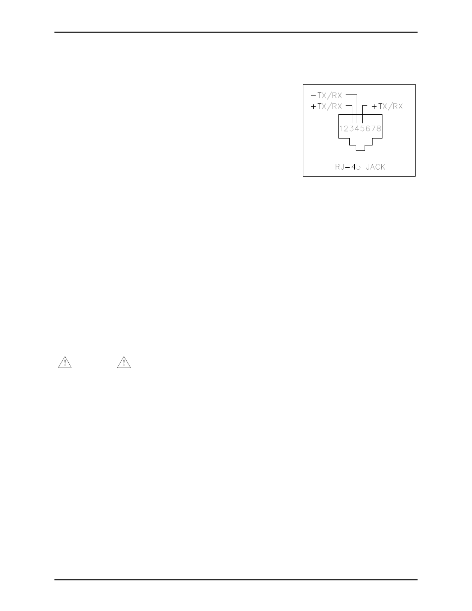
Field Wiring
Data (TX/RX)
An eight-pin data port (RJ45 jack) on the rear of the unit connects the
access panel data line to the ADVANCE system control cabinet.
A twisted pair cable (minimum Category 3) should be used for this
connection.
Observe cable conductor polarity (+/−) when making connections at
the control cabinet: (+ connects to + and − connects to −). No
damage will occur if the polarity is reversed, but the access panel will
not function. Maximum cable distance to the control cabinet is 3 km
when using No. 24 AWG (Category 3) cable.
Refer to Figure 3 for RJ45 jack pin out detail and Figure 5 for the
data port location.
N
OTE
: Pin 5 (+) and pin 4 (−) should be used for new installations. Pin 3 (+) and pin 4 (−) are used
when replacing a Model 727-001 Desktop Access Panel.
Power
The access panel is supplied with a 120 V ac/12 V dc wall plug power supply. Plug the power cord into
the power connector on the rear of the unit. Plug the other end into an ac electrical outlet (120 V ac @
50/60 Hz). Refer to Figure 5 for power connector location.
N
OTE
: The access panel does not have an on/off power switch and will power up immediately upon
plugging in the power cable. The ADVANCE control cabinet must also be powered and running before
the access panel is operational. LEDs on the access panel will flash, the sounder will “beep” and the
display will read “No communication with ADVANCE” until data communication is established with the
ADVANCE control cabinet.
WARNING
The power supply included with the Model 12576-503 or 12576-50315 Access
Panel is specifically designed for this unit and must not be used with any other 12576 series or 727 series
Desktop Access Panels.
Ground
A customer ground for additional ESD protection is located on the back of the unit. Ensure the unit is
properly grounded in accordance with local and national electrical code guidelines.
Figure 3. Data Connection Detail