Available adjustments, Front cover reattachment – GAI-Tronics ICS Zone 2/22 Weatherproof Page/Party Station User Manual
Page 2
Pub. 42004-734L2DQG
ICS Zone 2/22 Weatherproof Page/Party
®
Station Quick Installation Guide
Page 2 of 2
f:\standard ioms - current release\42004-xxxxqg quick guides\42004-734l2dqg.doc
11/14
Available Adjustments
Most optional equipment is preconfigured to a default standard at the factory. The following is a
partial list of the available adjustments and settings that may be needed:
Main PCBA
VLC Option
SmartSeries Option
Speaker Volume
Speaker Volume
FSK Transmit Level
Receiver Volume
VLC Override
Address
Transmit Level
Test Tone
Mutual Muting
Page Control
Termination PCBA
Remote Signaling
Speaker Impedance
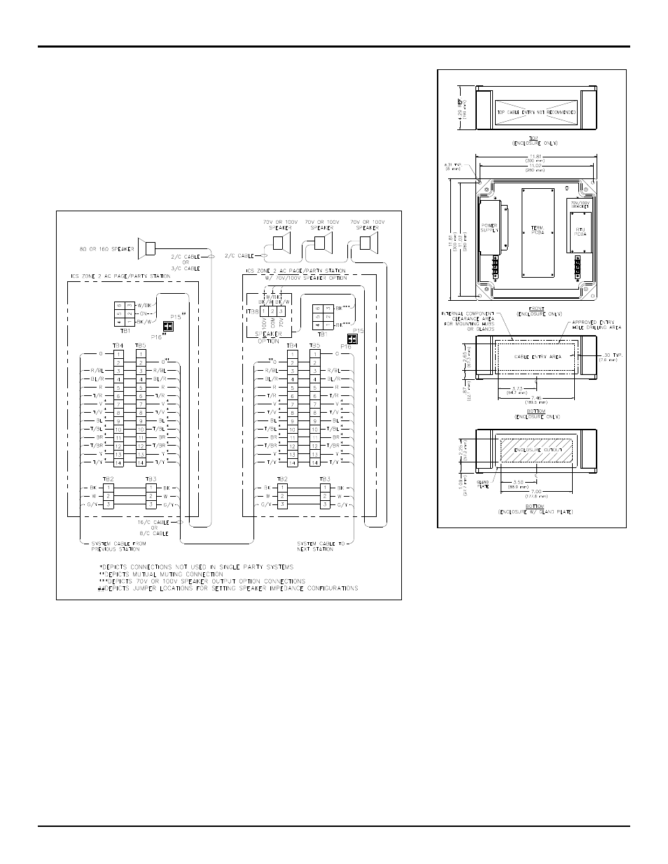
Figure 3. Typical installation wiring configuration
N
OTE
: Station input power can be through system cable or through a separate power source cable.
See Pub. 42004-734L2 for the possible beacon, RTU activation, dc option, and speaker impedance
configurations.
Front Cover Reattachment
Connect any cable harnesses that were disconnected during mounting. Place the front cover inside the rear enclosure, being careful not to pinch any
cables. Attach the front cover with the four screws and washers provided. Torque the screws to 50 in-lbs (5.65 n-m).
CE Mark
Certificate No.
Notified Body ID No. 0539
UL International DEMKO A/S
Lyskear 8
DL-2730 Herlev
Denmark
DEMKO 10 ATEX 1010664x .............................................. II 3 G Ex ic nA IIC T4 Gc and II 3 D Ex ic tb IIIC T135ºC Dc
IECEx UL 10.0038x ............................................................. Ex ic nA IIC T4 Gc and Ex ic tb IIIC T135ºC Dc
Figure 2. Suggested wire
entry locations