Connecting to the addressable amplified speaker, Connecting to the rf call box – GAI-Tronics XB001 Weatherproof Long-Life Battery Enclosure User Manual
Page 5
Pub. 43004-033A
Model XB001 Weatherproof Long-Life Battery Enclosure
Page: 5 of 5
\\s_eng\gtcproddocs\radio products-current release\43004\43004-033a\43004-033a.doc
08/08
Connecting to the Addressable Amplified Speaker
1. The Addressable Speaker is shipped with only two of the six screws securing the front section to the
rear. Back out the two screws and separate the two sections, carefully setting aside the front section.
Refer to GAI-Tronics Pub. 43004-030 for more detail.
2. Insert the lugged end of the (provided) weatherproof plug cable assembly through the existing cable
bushing located on the bottom of the speaker housing’s rear section. Wrap electrical tape around the
cable where it enters the bushing until it has a minimum diameter of 0.25 inch, allowing
approximately 10 inches of cable to remain inside the speaker housing. Tighten the bushing around
the cable.
3. Connect the 3/16-inch male quick-connect fastons from the weatherproof plug cable assembly to the
existing 3/16-inch fastons already attached to the speaker’s 11-point terminal strip plug. It is
extremely important to follow the color code noted in Figure 3. Failure to match red to red and
black to black could result in damaged circuitry.
4. Mount the rear section of the enclosure within two feet of the battery box and attach the speaker front
as described in Pub. 43004-030.
5. Insert the speaker cable plug into the receptacle located on the upper left side of the battery enclosure.
Connecting to the RF Call Box
1. Install the customer-provided weather-tight cable bushing in the bottom (right side) of the Call Box
rear section.
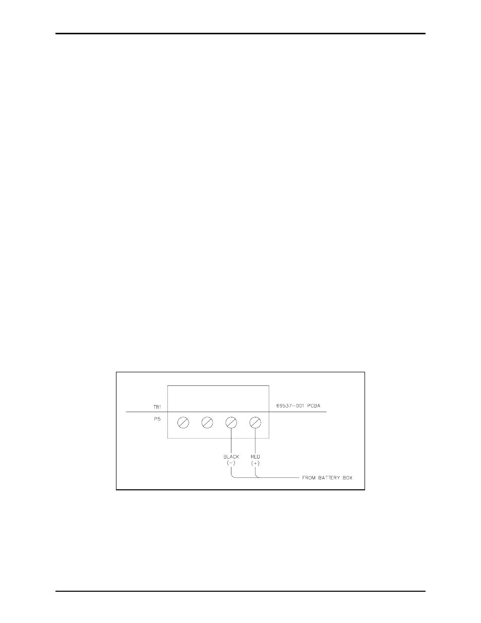
2. Remove the lugs from the weatherproof plug assembly, strip the wire insulation 1/8 inch, and insert
the cable through the previously installed cable bushing. Allow enough cable inside the enclosure to
connect the power input terminal strip (P5), located on the PCBA, with the door open. Secure the red
and black wires as noted in Figure 4 below:
Figure 4.
3. Close the Call Box door and tighten the screws using 16 to 20 inch-pounds of torque.
4. Mount the External Battery enclosure close enough to the RF Call Box mounting location to allow the
plug cable assembly to be connected to the receptacle located on its upper left side.