GAI-Tronics 12505-001 Repl. Door Assembly User Manual
Page 2
Pub. 42003-008A
M
ODEL
12505-001
R
EPLACEMENT
D
OOR
K
IT
Page:
2 of 2
\\s_eng\gtcproddocs\standard ioms - current release\42003 kit manuals\42003-008a.doc
6/96
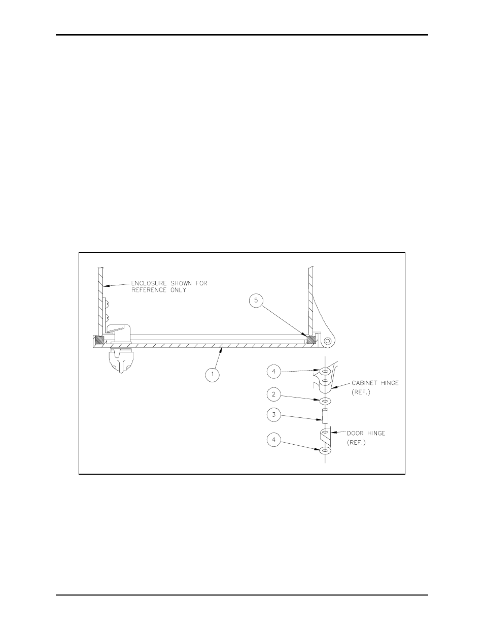
3. After ensuring proper fit and clearance, slide one pin retainer (item 4) onto each hinge pin (item 3).
Position the pin retainer such that it is 1/16 inch from the end of the hinge pin.
4. Position the door assembly onto the enclosure and place one washer (item 2) between the upper door
boss and the enclosure boss. In an upward position, insert the pin, with the retainer installed, through
hinge pin holes of the enclosure boss, washer, and door boss.
5. Insert the lower hinge pin, with the retainer installed, in a downward direction through the hinge pin
holes in the enclosure boss, washer and door boss.
6. Install the upper pin retainer by placing it on top of the upper hinge pin and then pushing downward
with the ¼-inch hex nut driver, while at the same time applying pressure at the bottom of the hinge
pin. The pin retainer should be pushed onto the hinge until both pin retainers are touching the bosses
of the door and enclosure.
7. Place the pin retainer on the opening of the ¼-inch hex nut driver and by pushing upward, install onto
the lower hinge pin, while applying downward pressure on the hinge pin. Pin retainers should touch
the bosses of the door and enclosure.
Figure 1.