Installing the new harness assembly – GAI-Tronics 12552-001 Rotary Switch Harness Assembly User Manual
Page 2
Pub. 42003-122A
M
ODEL
61504-053
R
OTARY
S
WITCH
H
ARNESS
R
EPLACEMENT
K
IT
Page:
2 of 2
f:\standard ioms - current release\42003 kit manuals\42003-122a.doc
01/12
Installing the New Harness Assembly
N
OTE
: Steps 1–3 may not be required depending on when the unit was manufactured.
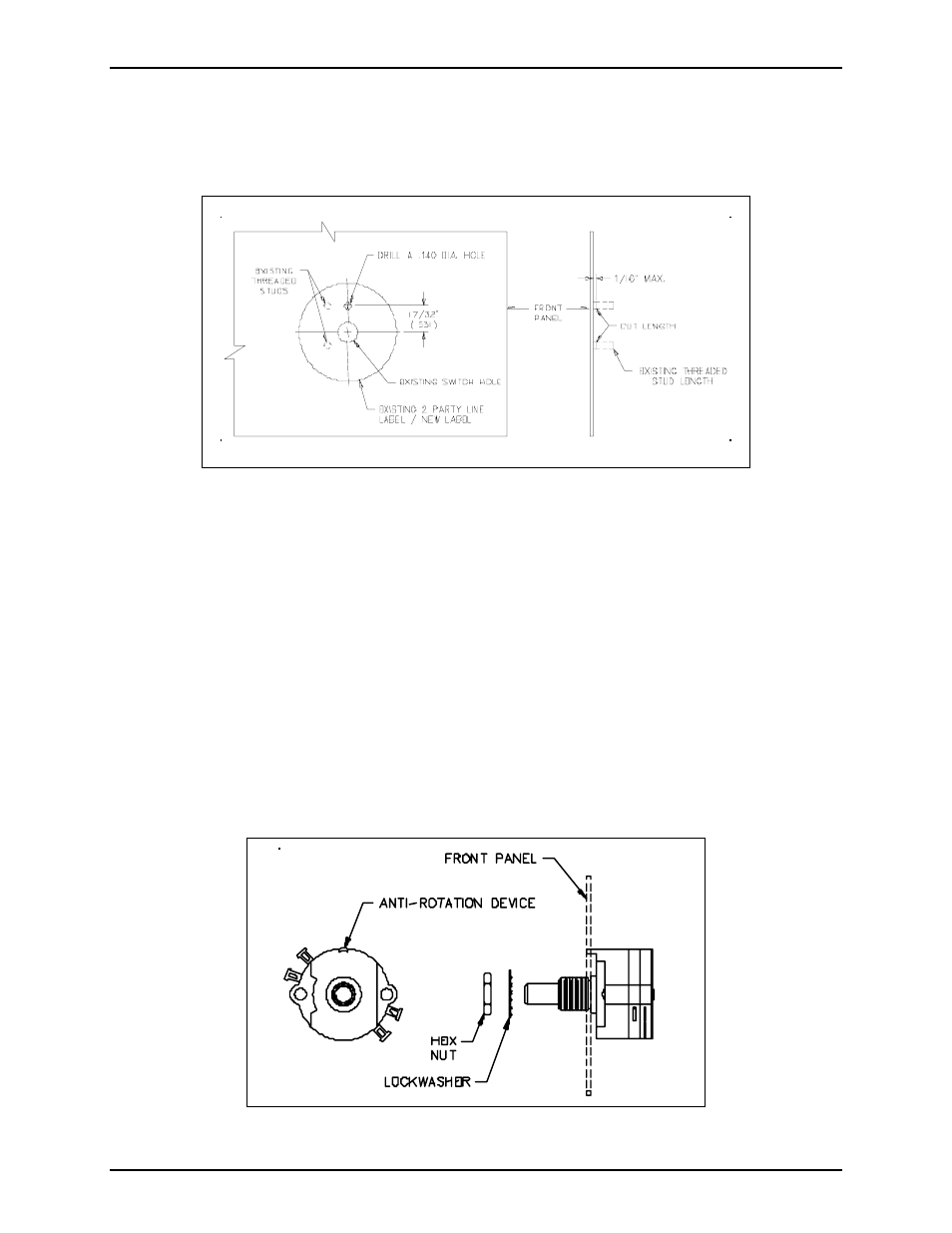
1. Drill a 0.140-inch (3.56 mm) hole in the front panel as shown in Figure 1.
Figure 1. Front Panel Modifications
2. Cut the threaded studs as shown in Figure 1.
3. Attach the two-party line label on the exterior of the front panel as shown in Figure 1.
4. Install the switch using the supplied hardware to the front panel as shown in Figure 2. The
anti-rotation device MUST go into the 0.140-inch (3.56 mm) drilled hole.
5. Reconnect the connector to the post header marked
J3
,
PARTY LINE SELECT
.
6. Place the party-line selector knob over the top of the switch assembly.
7. Use a pair of pliers to tighten the hex nut, and to secure the party-line selector knob.
8. Snap the cap into the party-line selector knob.
9. Close the subset using the four screws from Step 5 in the previous section.
Figure2. Switch Assembly