GAI-Tronics 12607-002 Party-Line Selector Knob Replacement Kit User Manual
Page 2
Pub. 42003-174
M
ODEL
12607-002
P
ARTY
-L
INE
S
ELECTOR
R
EPLACEMENT
K
IT
Page:
2 of 2
\\s_eng\gtcproddocs\standard ioms - current release\42003 kit manuals\42003-174.doc
5/99
6. Insert the new selector switch assembly through
the panel.
7. Insert a lock washer over the switch shaft and
secure with a nut.
8. Place the new knob over the selector switch
assembly.
9. Adjust the knob pointer position.
10. Tighten the nut against the lock washer in the
knob.
11. Insert the new cap into the top of the knob.
12. Reconnect the ribbon cable to the selector switch
assembly PCBA.
13. Replace the four cover screws.
Model 7265-101 Desktop Subset
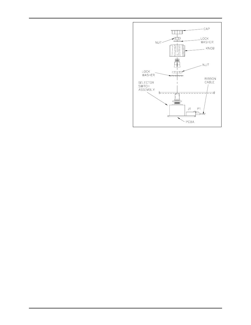
Refer to Figure 1.
1. Remove the top chassis from the base of the unit by removing the four screws from the bottom of the
subset. Save for re-assembly.
2. Disconnect the ribbon cable from the selector switch assembly PCBA.
3. Pop the cap out of the top of the knob and discard the cap.
4. Remove the nut, lock washer, and knob. Note pointer position when removing and ensure that the
pointer is reinstalled in the same position.
5. Remove the remaining nut and the lock washer and remove the old selector switch assembly. Save the
nut and lock washer for re-assembly.
6. Insert the new selector switch assembly through the front panel.
7. Insert the lock washer over the selector switch assembly shaft and secure with the nut.
8. Place the new knob over the selector switch assembly.
9. Adjust the knob pointer position.
10. Tighten the nut against the lock washer in the knob.
11. Insert the new cap into the top of the knob.
12. Reconnect the ribbon cable to the selector switch assembly PCBA.
13. Secure the chassis to the base using the four screws.
Figure 1. Knob Assembly View