GAI-Tronics 12562-103 SMART Emergency Phone PCBA Replacement Kit User Manual
Page 3
Pub. 42003-198B
M
ODEL
12562-103
S.M.A.R.T.
E
MERGENCY
T
ELEPHONE
PCBA
R
EPLACEMENT
K
IT
Page:
3 of 4
f:\standard ioms - current release\42003 kit manuals\42003-198b.doc
04/09
Models 297-003 and 298-003
Removing the Old PCBA
1. Use the Model 233-001 Tamper-Resistant Screwdriver to remove the six front panel screws and
remove the panel from its back box after disconnecting the telephone line.
2. Disconnect the microphone, speaker, switches, LED indicator, and keypad cables (Model 298-003
only) from the PCBA. Record the location of each connection for later reconnection.
3. Disconnect the red and green wires from the telephone line connection on the PCBA. Save the modular
cord.
4. Unscrew the four screws securing the PCBA. Save the screws.
Installing the New PCBA
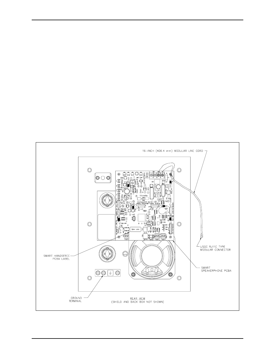
1. Align the holes in the four corners of the new PCBA with the standoffs in the telephone, maintaining
proper orientation. See Figure 2.
Figure 2. Model 297-003 and 298-003 PCBA Detail