GAI-Tronics 12562-104 SMART Handset Phone PCBA Replacement Kit User Manual
Page 3
Pub. 42003-201B
M
ODEL
12562-104
S.M.A.R.T
H
ANDSET
T
ELEPHONE
PCBA
R
EPLACEMENT
K
IT
Page:
3 of 5
f:\standard ioms - current release\42003 kit manuals\42003-201b.doc
04/09
Models 246-003, 247-003, 256-003, and 257-003
Removing the Old PCBA
1. Use a Phillips screwdriver to remove the four front panel screws and remove the panel from the
enclosure after disconnecting the telephone line.
2. Disconnect the handset, hookswitch, push button, keypad (Models 246-003 and 256-003 only), and
ringer cable(s) from the PCBA. Record the location of each connection for later reconnection.
3. Disconnect the red and green wires from the telephone line connection on the PCBA. Save the
modular cord.
4. Depress the locking tab on each nylon standoff while lifting up on that corner of the PCBA to remove
it.
Installing the New PCBA
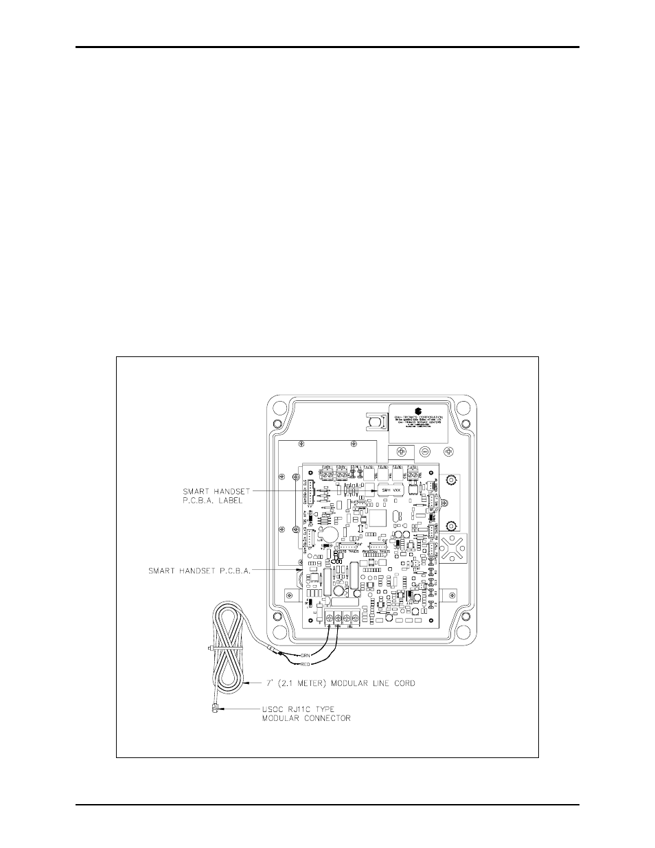
1. Align the holes of the new PCBA with the snap-on nylon standoffs in the telephone, maintaining
proper orientation. See Figure 2.
Figure 2. PCBA Connections for Models 246-003, 247-003, 256-003, and 257-003