Enclosure configuration – GAI-Tronics 110438-001 Intrinsically-Safe Microphone Barrier Kit User Manual
Page 3
Pub. 42003-209B
M
ODEL
10438-001
I
NTRINSICALLY
-S
AFE
M
ICROPHONE
B
ARRIER
K
IT
Page:
3 of 6
\\s_eng\gtcproddocs\standard ioms - current release\42003 kit manuals\42003-209b.doc
06/06
WARNING
Insure proper grounding to protective earthing.
Do not disconnect equipment while energized.
Inspect and clean the machined flange flame joint surfaces of both the cover and box. Surfaces must be
smooth, free of nicks, scratches, dirt or any foreign particle build-up that would prevent a proper seal.
Surfaces must seat fully against each other to provide a proper explosion-proof joint. Clean surfaces by
wiping with a clean lint-free cloth.
Make certain no cover bolts are omitted. Use only those bolts supplied with the enclosure.
N
OTE
: The recommended torque setting for tightening the cover bolts is 8 ft-lbs (10.8 N-m)
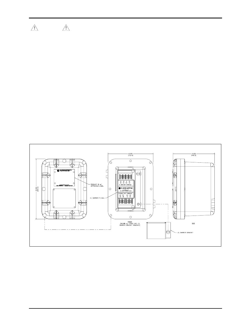
Enclosure Configuration
The Model 10438-001 I.S. barrier enclosure contains a single PCBA where all customer connections are
made. The barrier bracket covers the intrinsically-safe terminals. Remove the bracket before connecting
the I.S. wires to the PCBA. Reattach the bracket after wiring and ensure the bracket is tight against the
bottom of the enclosure. All connections should be properly lugged. The enclosure itself has eight cover
mounting bolts around the perimeter. The cover of the enclosure contains all applicable approval
labeling.
Figure 2. Model 10438-001 Microphone I.S. Barrier Kit Mounting Details and Conduit Entries