GAI-Tronics 12803-001 RigCom PCBA Replacement Kit User Manual
Page 2
Pub. 42003-214B
M
ODEL
12803-001,
-002,
&
-003
R
IG
C
OM
PCBA R
EPLACEMENT
K
ITS
Page
2 of 2
e:\standard ioms - current release\42003 kit manuals\42003-214b.doc
04/14
8. Attach the nylon spacer to the back of the PCBA.
9. Place the PCBA into the rear enclosure, lining up the four holes.
10. Secure the PCBA with the four screws.
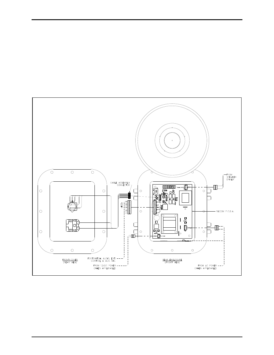
11. Plug all of the connectors into the new PCBA. See Figure 1.
12. Plug the cable assembly connector from the front cover into the PCBA in the rear enclosure.
13. Close the front cover and screw the 12 bolts back into the enclosure. The recommended torque
setting for the cover bolts is 17 ft-lbs (23 N-m).
Figure 1. PCBA Replacement Diagram
N
OTES
:
1. Either 120 V ac power or 12 V dc may be connected to the Model 400-003 RigCom. Under no
circumstances should ac and dc power be connected to the Model 400-003 at the same time.
2. Either 230 V ac power or 12 V dc may be connected to the Model 400-004 RigCom. Under no
circumstances should ac and dc power be connected to the Model 400-004 at the same time.