GAI-Tronics 12587-104 ICS Subset-to-ICS Page/Party Amplifier 15-Foot Cable Assembly User Manual
Page 2
Pub. 42003-233B
M
ODEL
12587-104
ICS
S
UBSET TO
ICS
P
AGE
/P
ARTY
®
A
MPLIFIER
15-F
OOT
C
ABLE
A
SSEMBLY
Page:
2 of 2
f:\standard ioms - current release\42003 kit manuals\42003-233b.doc
03/11
2. Route the 15-foot cable assembly through the wall or conduit from the ICS amplifier enclosure to the
subset location or wall receptacle.
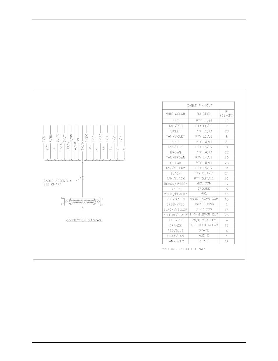
3. Install the supplied spare DB25 connector onto the stripped and tinned wires side of the cable
assembly. Place the stripped wire ends into the solder cups in a manner that allows the exposed wire
to bottom out against the base of the solder cup. Solder all wires from the cable to the DB25
connector. See Figure 2 for wire color terminations.
4. Arrange the cable so that the soldered DB25 connector plugs into the subset or ICS subset extension
cable. Plug the DB25 connector into the rear of the ICS subset or extension cable and secure the
thumb screws from the female DB25 connector.
Figure 2. Wire Color Terminations