Installation – GAI-Tronics 12577-011 and 12577-018 Access Panel-to-Fiber Interface Kits User Manual
Page 2
Pub. 42003-262A
M
ODEL
12577-011
&
12577-018
A
CCESS
P
ANEL
-
TO
-F
IBER
I
NTERFACE
K
ITS
Page
2 of 4
e:\standard ioms - current release\42003 kit manuals\42003-262a.doc
11/13
The indoor single card housing is constructed of powder coated 16-gauge steel and can be mounted on
standard DIN rail or wall mounted.
The outdoor dual card housing is a plastic enclosure that can be mounted to a wall or pole. It has an
internal power adapter inside that accepts ac or dc voltage input with a 24 V dc output to the Fiber Optic
Link card. The outdoor card housing should be mounted to a wall or pole with the three screws provided.
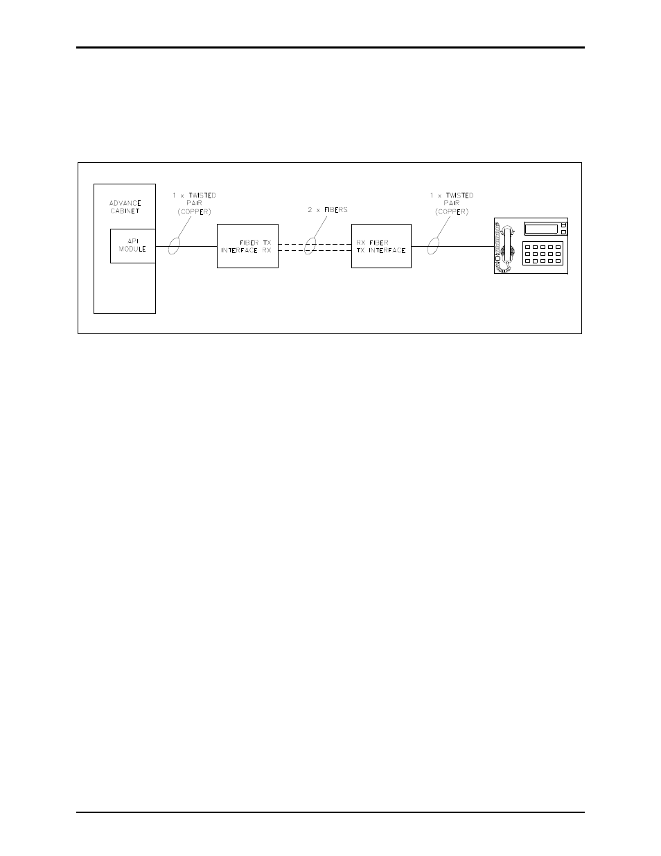
Figure 1. Typical Block Diagram
Installation
1. Mount the indoor card housing to the provided DIN rail. Mount the outdoor dual card housing with
the three screws provided. See Figure 3 for mounting details.
2. Compress the plastic card guide latch on the right side of the PCBA to slide it out partially from the
housing. Carefully slide the card out of the housing to make the following connections to the PCBA.
Refer to Figure 2 for data card connectors and LEDs. The PCBA should not need to be removed
from the housing to make the connections.
3. Connect fiber optic cable to card. Connect fiber to the transmit and receive terminals marked TX and
RX. Fiber cable should always be routed loosely avoiding tight bends.
4. Connect the copper pair from the ADVANCE cabinet API module or the access panel by connecting
to the black TIP and RING screw-down terminals.
5. Connect a 24–56 V dc (70mA minimum) power source to the 48 V dc terminal on the PCBA.
6. Slide the card back into the housing and lock into place.
7. Close the outdoor housing and secure with lock.