Opening the station, Installing the termination pcba – GAI-Tronics 12831-007, 12831-008 Hazardous Area ICS Termination PCBA Upgrade Kits User Manual
Page 2
Pub. 42003-268A
M
ODEL
12831-007
&
12831-008
H
AZARDOUS
A
REA
ICS
T
ERMINATION
PCBA
U
PGRADE
K
ITS
Page
2 of 6
f:\standard ioms - current release\42003 kit manuals\42003-268a.docx
02/14
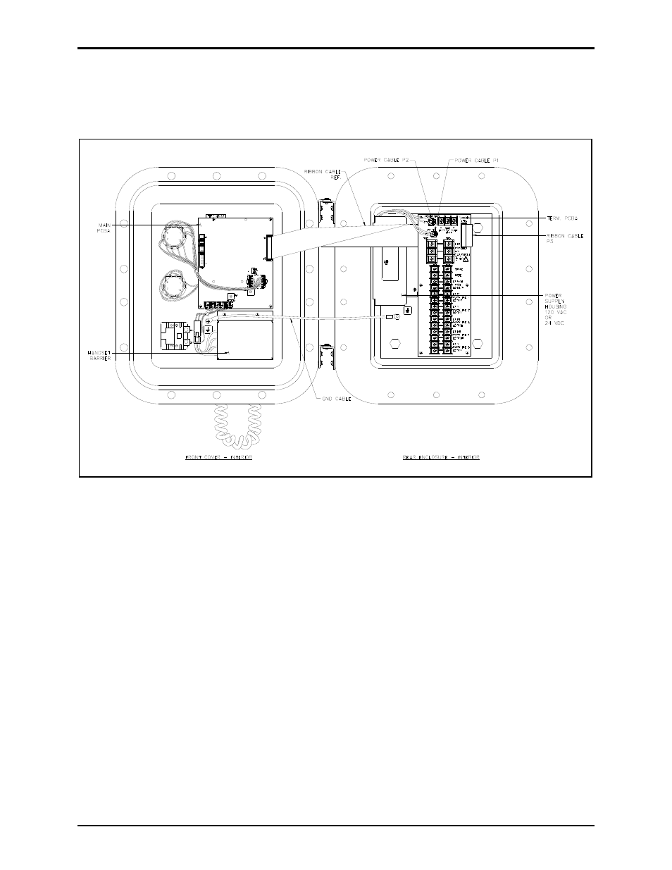
Opening the Station
Remove all cover bolts from the enclosure. Swing the front door open to access the internal PCBAs. See
Figure 1.
Figure 1. ICS Hazardous Area Station – Interior View
Installing the Termination PCBA
1. On the Termination PCBA, unplug the ribbon cable at P3, and the power cables at P1 and P2.
2. Remove the six screws that secure the Termination PCBA to the rear mounting plate and remove the
Termination PCBA. Keep the ribbon cable routed under the insulator.
3. Remove the two screws that secure the power supply housing to the rear mounting plate.
4. Unplug the input power cable assembly from the ac or dc power supply. The ac power connector is a
three-position plug and the dc power connector is a five-position plug.
5. Plug in the new input power cable assembly provided with the kit into the power supply.
6. Reattach power supply housing to the rear mounting plate with two screws, routing the wires behind
the power supply and housing.
7. Attach the new Termination PCBA to the rear mounting plate with six screws.
8. Place the upgrade kit label on the power supply housing as shown in Figure 2.