GAI-Tronics XCP0010A DC Control Kit User Manual
Page 3
Pub. 43003-012B
Model XCP0010A DC Control Kit
Page: 3 of 4
11/02
5. Mount the XCP0010A DC Control Option CDC PCBA to the appropriate slave PCBA (1, 2, or 3) and
channel (1, 2, 3, or 4 for each PCBA). The CDC PCBA must be mounted on the bottom side of the
slave panel.
6. Remove the shunt and connect the 2-pin connector P62X on the CDC PCBA to the appropriate
header on the slave PCBA (JU620, JU621, JU622 or JU623).
7. Connect the-pin connector P2X to the 14-pin header (P26, P27, P28, or P29) on the CSD PCBA.
8. Fasten the CDC PCBA to the inner PCBA mounting plate using the 3 supplied #4-40 screws. See
Figure 2.
9. After the PCBA has been properly mounted, you may reassemble the console by reversing the
disassembly procedure. Verify that all CSD-to-main board ribbon cables are properly positioned into
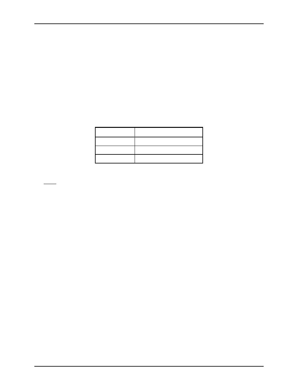
their protective guides and connected to their respective main board connectors as follows:
Channel
Main Board Connector
1-4
P1
5-8
P2
9-12
P3
Main Board-to-CSD Slave Board Connectors
Note: The XCP0010A DC Control board has been factory-calibrated to provide the standard control
currents and does not normally require field adjustment.
10. Reconnect power to the ICP9000 Series Desktop Console.
After the console has been reassembled, it is necessary to program the console by editing the channel
parameters. Refer to your CARD Suite Software (XAC1000A) for specific programming instructions.
Also refer to the ICP9000 Series Desktop Console Operator’s Manual, 43004-016, for user instructions
on dc control operation.
ICP9000 Navigator Series MCU
1. Disconnect power from the ICP9000 Navigator Series MCU.
2. Remove the 10 screws securing the side cover panel and gently lift the cover exposing the attached
speaker cable and master display cable. See Figure 3 on page 4.
3. Disconnect all plugs attached to the inner PC board mounting plate. See Figure 3. Then remove the 4
screws attaching the mounting plate to the base. This allows you to remove the mounting plate.
4. Mount the XCP0010A DC Control Option CDC PCBA to the appropriate slave PCBA (1, 2, or 3) and
channel (1, 2, 3, or 4 for each PCBA). The CDC PCBA must be mounted on the bottom side of the
slave panel.
5. Remove the shunt and connect the 2-pin connector P62X on the CDC PCBA to the appropriate
header on the slave PCBA (JU620, JU621, JU622, or JU623).
6. Connect the-pin connector P2X to the 14-pin header (P26, P27, P28, or P29) on the CSD PCBA.