Icp9000 navigator series mcu – GAI-Tronics XCP0140A Headset Interface Kit User Manual
Page 2
Pub. 43003-025B
Model XCP0140A Headset Interface Kit
Page: 2 of 3
11/02
ICP9000 Navigator Series MCU
Note: The headset interface assembly jack was designed for mounting beneath a horizontal surface or on
an edge.
1. Remove the rear panel.
2. Remove the Navigator control ribbon cable from the PPI on the Navigator board and PPI on the main
board. Keep the cable for future use.
3. Position the shorting clips on PP2 to enable operation of the headset. This option must also be
enabled and the sensitivity of the headset microphone set in the User Parameter Menu as described in
the Console Diagnostics section of the Installation and Service Manual, Pub 43004-025.
4. The headset jack plugs into the modular-styled headset jack (P9) at the back of the MCU.
Note: This jack is not labeled on this product.
For left-hand mounting, follow the steps below:
1. Detach the endcap with the plug receptacles by removing the 2 screws located on underside of the
headset interface.
2. Remove the other endcap by gently pushing on it from the inside of the unit.
3. Flip the endcaps, reattach the screws, and the headset interface can now be mounted to the left side.
See Figure 2.
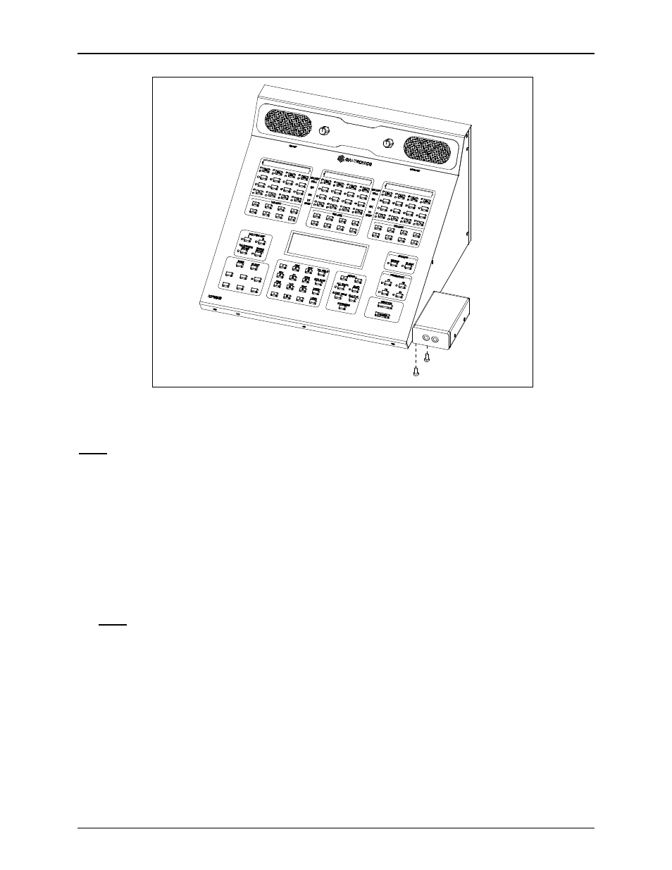
3. Plug the modular connector into the rear of the console at the H
EADSET
/H
ANDSET
jack, or on the
MCU at jack (P9, which is not labeled).
Figure 1.