GAI-Tronics SPK200 Solar Panel Interface Kit User Manual
Page 3
Pub. 43003-039A
M
ODEL
SPK200 S
OLAR
I
NTERFACE
K
IT
Page:
3 of 3
d:\radio products-current release\43003\43003-039a\43003-039a.doc
06/05
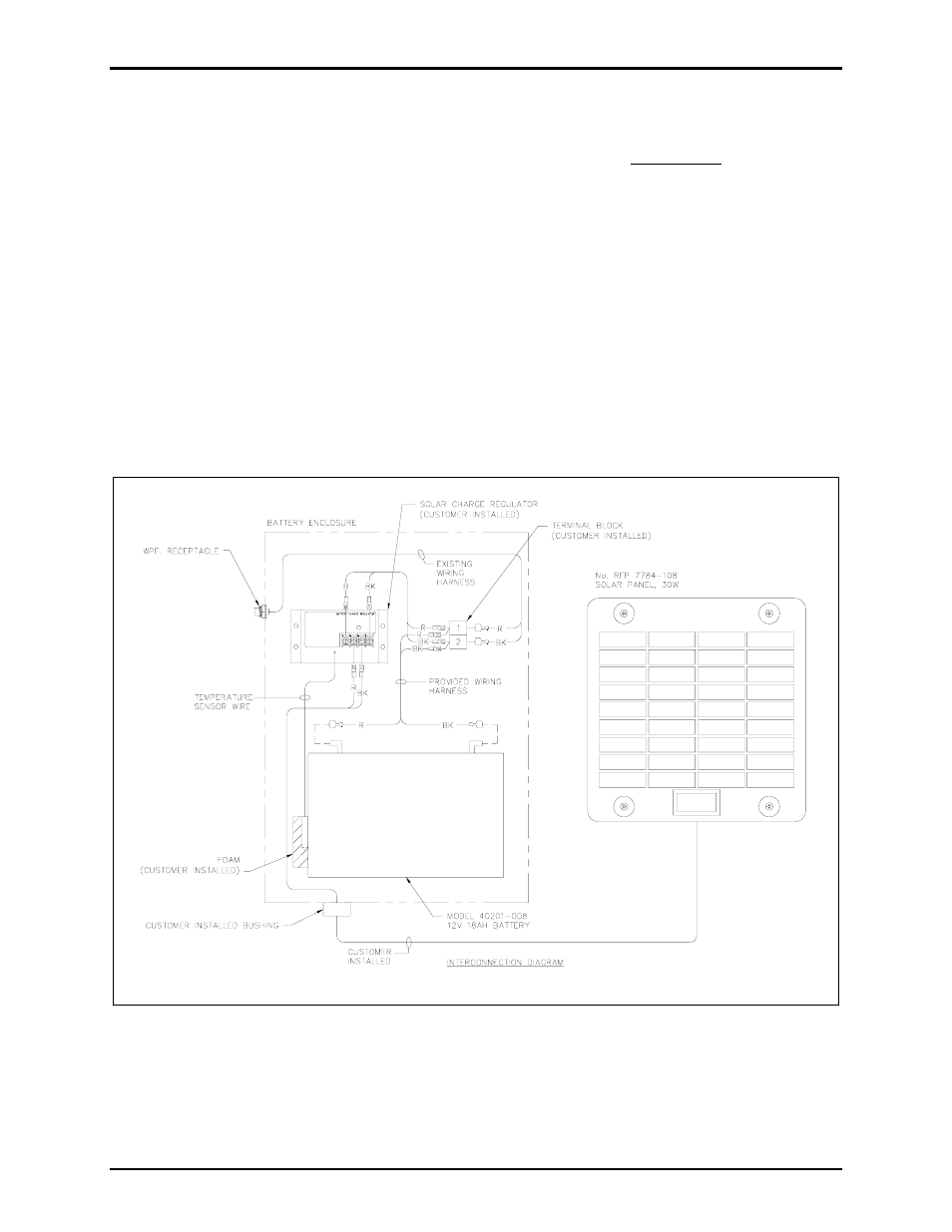
6. Connect the ¼-inch quick-connect fastons from the weatherproof receptacle harness to the terminal
strip.
7. Attach the charge regulator’s temperature sensor wire to the side of the fully charged battery using the
self-adhesive foam provided with the regulator.
8. After mounting the rear section of the enclosure, the solar panel cable can be installed. Refer to Pub.
43003-037 provided with the Model XB001 Kit for further information. Insert the solar panel cable
through the cable bushing, allowing enough slack to route the cable through the enclosure and
removing any excess cable. Attach to the charge regulator module. (The use of spade lugs is
recommended.) Tighten the bushing to insure retention of the rain-tight rating.
9. Return the door to the rear section by inserting the hinge pins and pushing into place, closing the
door. Re-install the four screws using 16 to 20 inch-pounds of torque.
10. Connect plug end of the wiring harness provided with the Model XB001 Kit to the weatherproof
receptacle and connect the lugged end to the terminal strip inside the Addressable Amplified Speaker.
If this solar power arrangement is used for GAI-Tronics’ RF Call Boxes, cut the lugs off the wires,
strip the insulation, and insert into the power connector on the Call Box PCBA.
Figure 2. Interconnection Diagram