W = white b = black g = green r = red – Geist Leak Detection Kit User Manual
Page 4
Leak Detection Kit quick setup guide (rev.131111B-GD)
4
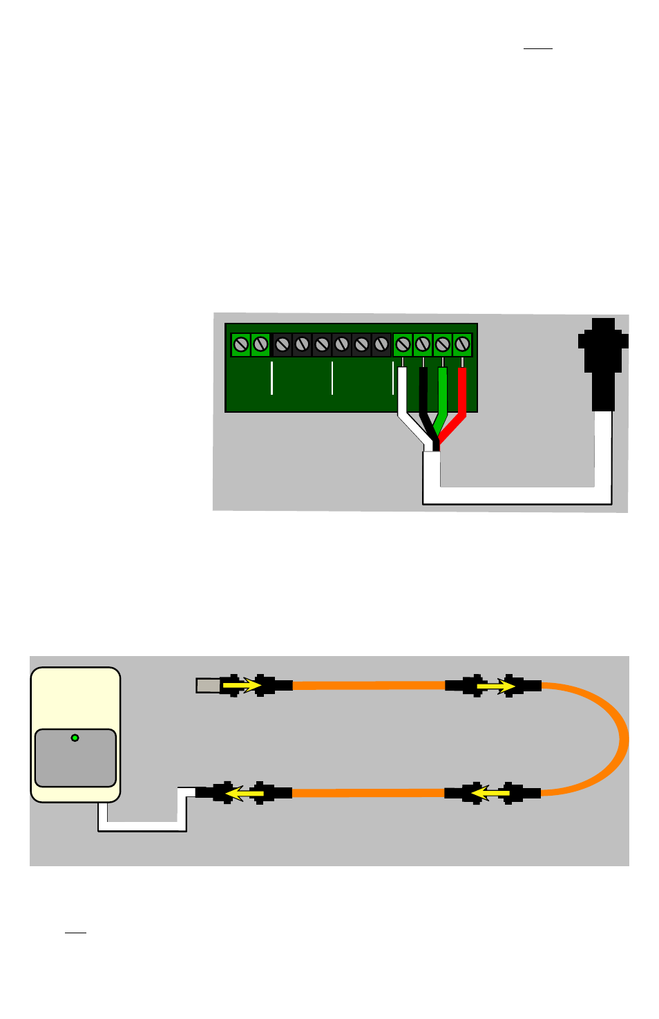
Ÿ Connecting the Leak-Detection Cable(s):
Your leak-detection kit will include one or more lengths of orange Leak-Detection Cable.
The cables are designed to be daisy-chained together, so each cable will have a 4-pin male
twist-lock plug on one end, and a 4-pin female twist-lock socket on the other. The first
length of Leak-Detection Cable connects to the Leader Cable from the LD300 Control
Box, and additional lengths (if any) are chained together as necessary.
Some kits are supplied with a cable that is permanently terminated at one end; if your kit
is one of these, then the terminated cable must be the last cable in the chain. If your kit
does not include a pre-terminated cable, then the Terminator Plug must be attached to the
last cable in the chain, as shown here.
Ÿ Connecting the Leader Cable:
The “Leader Cable” is a 15-foot (4.57m) white cable with a twist-lock connector at one end
and four bare, stripped and tinned wires at the other. To connect the Leader Cable, make
sure the four colored wires are stripped so that approx. ¼ inch (7mm) of bare wire is
showing, then insert the
wires into the appropriate
terminals of the CABLE
INPUT terminal block and
tighten the screws to lock
the wires into place, as
shown here.
5VDC
DC IN
–
+
NC
NC
NO
NO
C
C
FAULT
LEAK
CABLE
INPUT
B
W
R
G
W = White
B = Black
G = Green
R = Red
“Supervised” mode is recommended because if the LD300 loses power, both relays will
de-energize, resulting in a simultaneous “leak detection” and “cable fault” event being seen
by the monitoring unit which the LD300 is connected to. Since both of these conditions
can’t be true at the same time, the simultaneous occurrence of both events indicates that the
LD300 is no longer functioning. In “non-supervised” mode, you would not see any
relay-state change if the LD300 lost power, and wouldn’t have any way to know the unit
was no longer working. (Note: if you change this jumper setting, you must power-cycle the
LD300 for it to recognize the change.)
POWER/ALARM
LD300
first length of sensing cable
attaches to the leader cable
from the LD300 control box...
additional lengths
are daisy-chained
as necessary...
terminator plug (if required)
is attached to last length of
sensing cable in the chain.