Geist Leak Detection Kit User Manual
Page 6
Leak Detection Kit quick setup guide (rev.131111B-GD)
6
CONFIGURING THE MONITORING UNIT’S ANALOG-INPUT AND ALARM
THRESHOLD SETTINGS:
(note: these instructions assume that the Leak Detection Kit is connected to an RSE-series
or RSO unit with firmware v3.6.1 or higher, or a GBB-series unit with v1.5.1 or higher.)
The first step is to re-name the analog inputs to something more descriptive, to help
identify the “cable fault” and “leak” signals when looking at the unit’s logged data or
e-mailed alert messages. These names can be changed from the
Display
tab, in the section
titled
Analog Sensors
.
If you connected the signals
according to the examples above,
Analog 1 will be the “Cable Fault”
signal, and Analog 2 will be the
“Leak Detection” signal, so change
their
Friendly Names
as shown here,
then click
Save Changes
. (The
Min
and
Max
settings can be left at their defaults.) Change
the
Friendly Name
settings for the two analog inputs which the signals from the LD300
control box are connected to.
Next, go to the
Alarms
tab, and click the
Add New Alarm
button to create a new alarm entry.
Choose “
Cable Fault
” from the
list of measurements, then set the
trips if
and
threshold
entries to
Above
and
50
, as shown here.
Alarm must remain tripped for
should
be left at
0
; if you wish the unit to
repeatedly send alarm messages for
as long as the alarm condition
perists, set
Repeat Every
as desired.
(If not, leave it set to
0
or
No
5VDC
DC IN
–
+
NC
NC
NO
NO
C
C
FAULT
LEAK
CABLE
INPUT
B
W
R
G
striped wire is negative (–)
unstriped wire is positive (+)
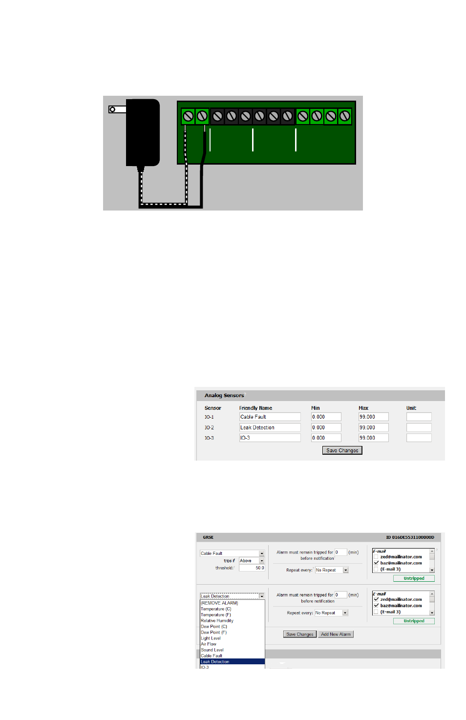
Ÿ Connecting the 5V power supply:
The LD300 Control Box is powered by a standard 5VDC wall transformer-style power
supply. Make sure both wires are stripped so that approx. ¼ inch (7mm) of bare wire is
showing, then insert the wires into the appropriate terminals of the 5VDC DC IN terminal
block and tighten the screws to lock the wires into place, as shown here.