Line disconnect switch -5 – Hypertherm H401 Power Supplies User Manual
Page 29
INSTALLATION
H401 & H601
Instruction Manual
3-5
5
L1
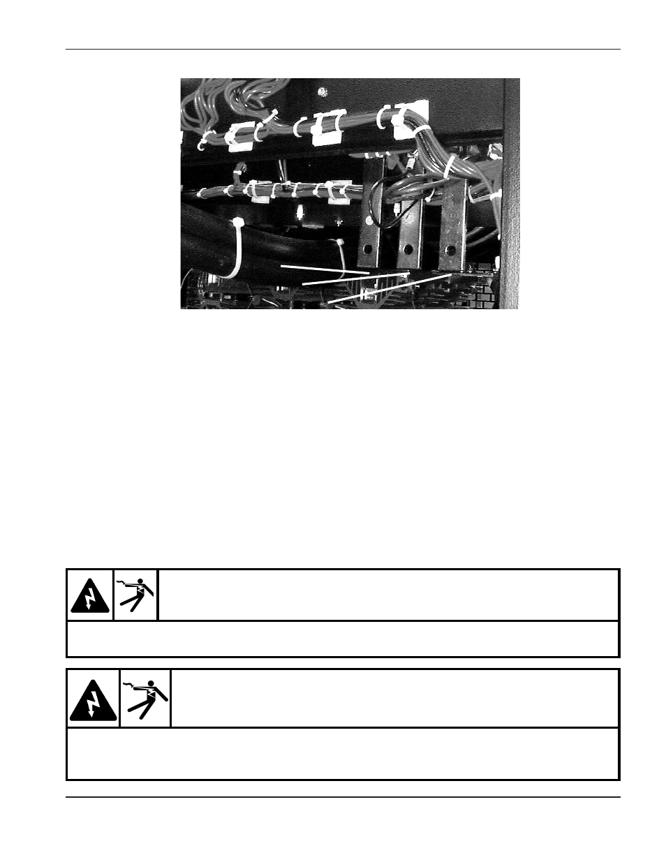
Line Disconnect Switch
The line disconnect switch serves as the supply voltage disconnecting (isolating) device. Install this switch on a
wall near the power supply (supplies) for easy accessibility by the operator. The line disconnect switch must be
installed by qualified personnel following all applicable national or local codes. The switch should:
• isolate the electrical equipment and disconnect all live conductors from the supply voltage when in the
“OFF” position
• have one "OFF" and one “ON” position clearly marked with “0” (OFF) and “1” (ON)
• have an external operating handle capable of being locked in the “OFF” position
• contain a power operated mechanism that serves as an emergency stop
• have slow-blow fuses installed for the proper breaking capacity
• have slow-blow fuses installed for the proper breaking capacity
• Provide power to only one power supply (parallel operation requires a seperate and unique disconnect
switch for each power supply)
Refer to the data plate on the rear of the power supply to verify the correct line voltage and current draw
requirements for the power supply.
L3
L2
WARNING
ELECTRICAL SHOCK CAN KILL
The line disconnect switch must be in the OFF position and remain in the OFF position for the
remainder of the installation of the H401 or H601 power supply.
WARNING
Parallel Systems
ELECTRICAL SHOCK CAN KILL
If the power supply is used in parallel with another power supply, or used as a slave unit with
another power supply, both line disconnect switches must be in the OFF position and remain in the
OFF position during installation and maintenance work.