IBASE MI980 User Manual
Page 24
Advertising
INSTALLATIONS
20
MI980 User’s Manual
Signal Name
Pin #
Pin #
Signal Name
3.3V
11
1
3.3V
-12V
12
2
3.3V
Ground
13
3
Ground
PS-ON
14
4
+5V
Ground
15
5
Ground
Ground
16
6
+5V
Ground
17
7
Ground
-5V
18
8
Power good
+5V
19
9
5VSB
+5V
20
10
+12V
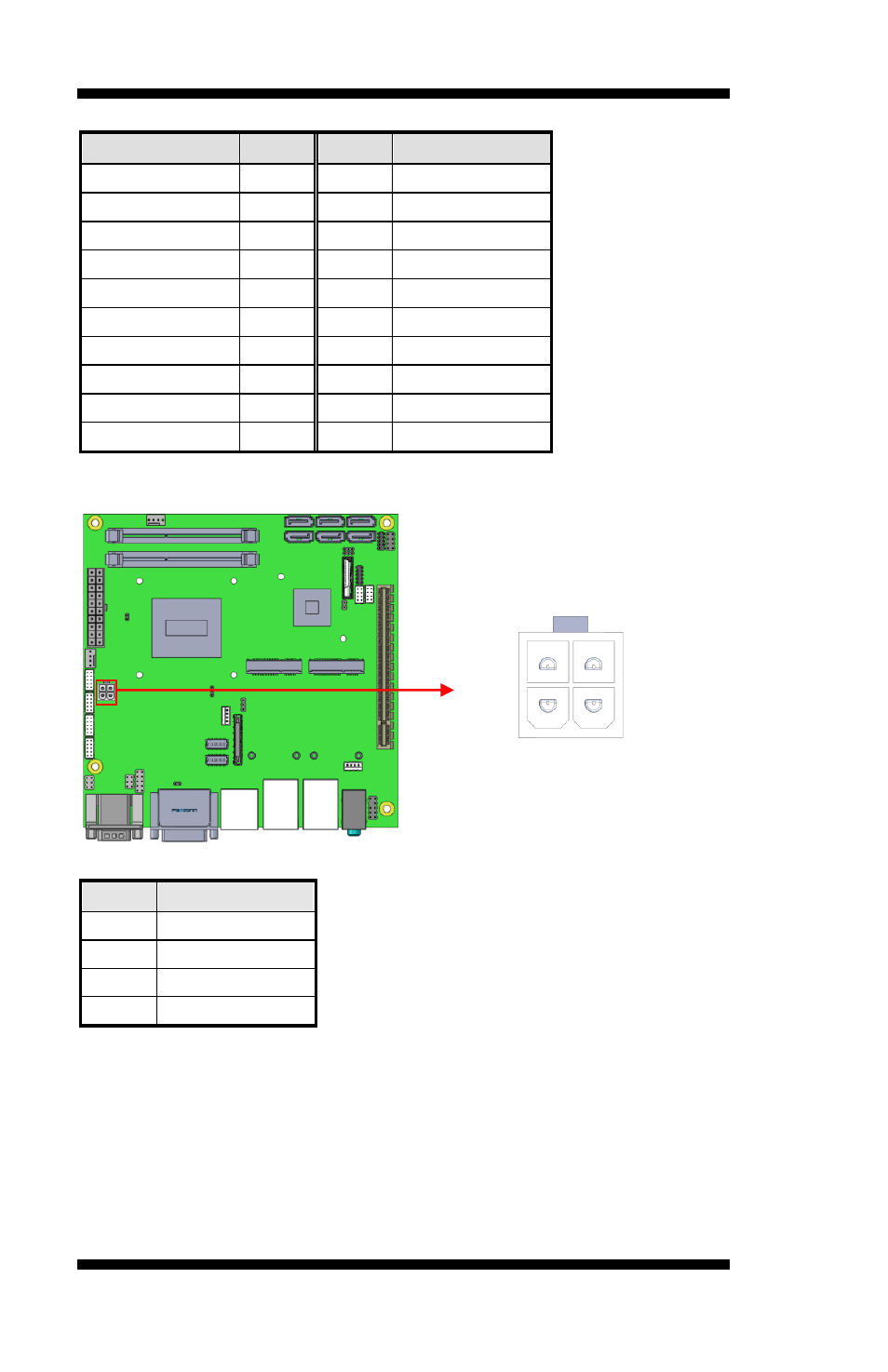
J6: ATX 12V Power Connector
This connector supplies the CPU operating voltage.
Pin #
Signal Name
1
Ground
2
Ground
3
+12V
4
+12V
JP7: LPC debug Connector (Factory use only)
JP9: SPI Flash Connector (Factory use only)
3
1
4
2
Advertising