Power led: pins 11 - 15 – IBASE MI946 User Manual
Page 23
Advertising
INSTALLATIONS
MI946F User’s Manual
19
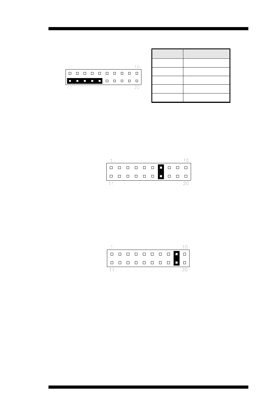
Power LED: Pins 11 - 15
Pin #
Signal Name
11
Power LED
12
No connect
13
Ground
14
No connect
15
Ground
ATX Power ON Switch: Pins 7 and 17
This 2-pin connector is an “ATX Power Supply On/Off
Switch” on the system that connects to the power switch on
the case. When pressed, the power switch will force the
system to power on. When pressed again, it will force the
system to power off.
Reset Switch: Pins 9 and 19
The reset switch allows the user to reset the system without
turning the main power switch off and then on again.
Orientation is not required when making a connection to this
header.
Advertising