Fan1: cpu fan power connector, Power led: pins 3 and 4, Pin # signal name 3 vcc 4 ground – IBASE IB825 User Manual
Page 19: Hard disk drive led connector: pins 5 and 6, Cn4: power input connector
INSTALLATIONS
IB825 User’s Manual
15
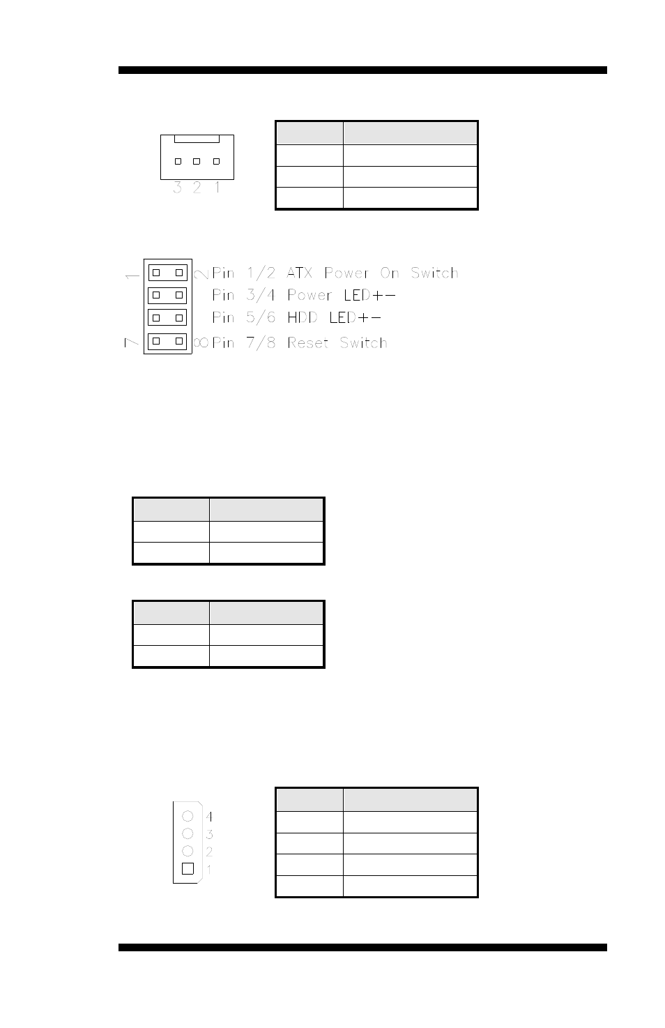
FAN1: CPU Fan Power Connector
Pin #
Signal Name
1
Ground
2
+12V
3
Rotation detection
J1: System Function Connector
ATX Power ON Switch: Pins 1 and 2
This 2-pin connector is an “ATX Power Supply On/Off Switch” on the
system that connects to the power switch on the case. When pressed, the
power switch will force the system to power on. When pressed again, it
will force the system to power off.
Power LED: Pins 3 and 4
Pin #
Signal Name
3
Vcc
4
Ground
Hard Disk Drive LED Connector: Pins 5 and 6
Pin #
Signal Name
6
HDD Active
5
Vcc
Reset Switch: Pins 7 and 8
J2, J3: SATA Connectors
CN4: Power Input Connector
Pin #
Signal Name
1
+12V
2
Ground
3
Ground
4
+5V
Remarks: It is strongly recommended that this power connector is
used in order to have more current available to 12V devices.