IBASE IB960 User Manual
Page 24
INSTALLATIONS
20
IB960F User’s Manual
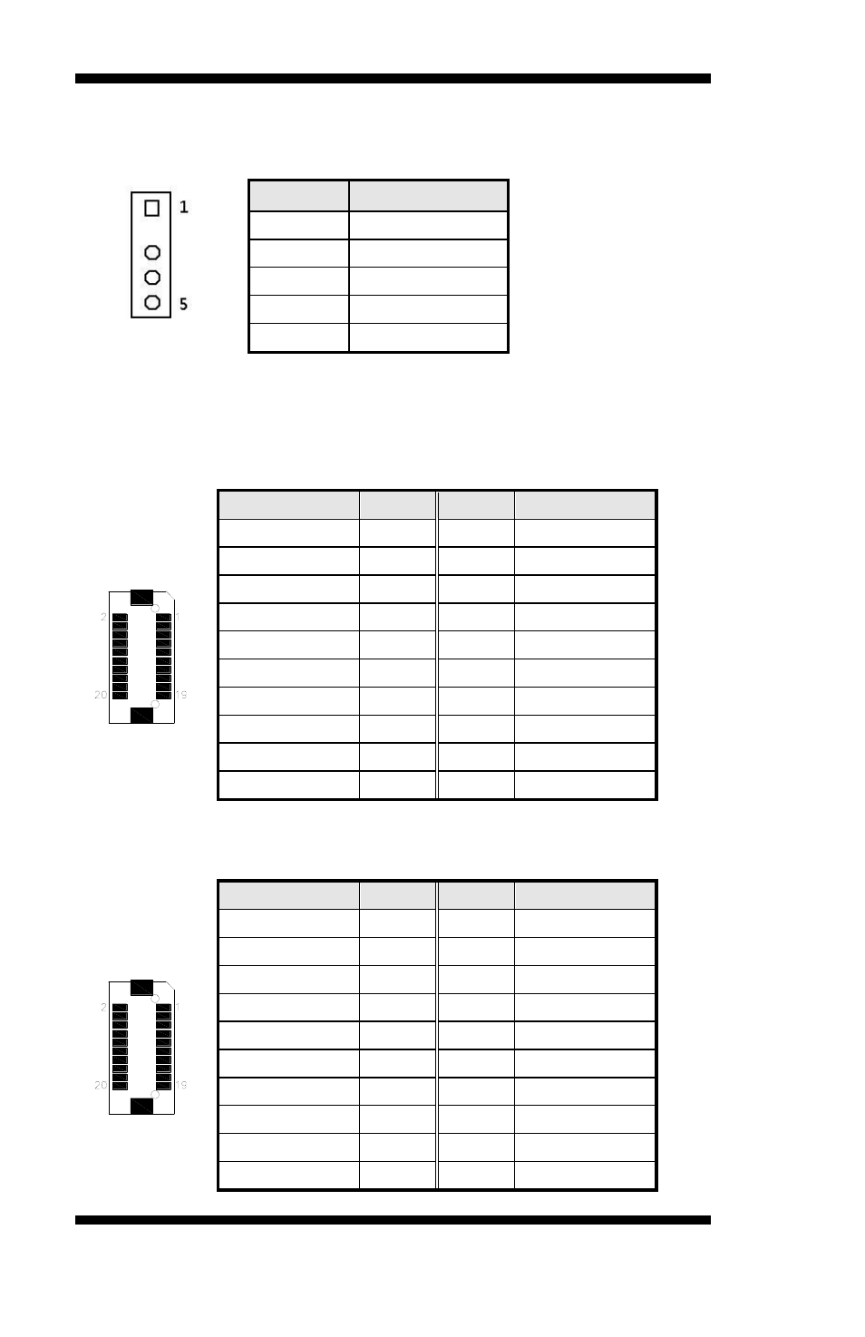
J20: External PS/2 Mouse Port
The following table shows the pin outs of the PS/2 mouse pin header.
Pin #
J20
1
Mouse data
2
N.C
3
GND.
4
Mouse clock
5
Vcc
J21, J22: LVDS Connector (2nd channel, 1st channel)
The LVDS connectors, DF13 20-pin mating connectors, are composed of
the 2nd channel (J21) and 1st channel (J22) to support 18-bit or 24bit
J22: first channel
Signal Name Pin #
Pin #
Signal Name
TX0-
2
1
TX0+
Ground
4
3
Ground
TX1-
6
5
TX1+
*5V/3.3V
8
7
Ground
TX3-
10
9
TX3+
TX2-
12
11
TX2+
Ground
14
13
Ground
TXC1-
16
15
TXC1+
*5V/3.3V
18
17
BKL_EN
+12V
20
19
+12V
*JP9 can be used to set 3.3V or 5V.
J21: Second channel
Signal Name Pin #
Pin #
Signal Name
TX4-
2
1
TX4+
Ground
4
3
Ground
TX5-
6
5
TX5+
*5V/3.3V
8
7
Ground
TX7-
10
9
TX7+
TX6-
12
11
TX6+
Ground
14
13
Ground
TXC2-
16
15
TXC2+
*5V/3.3V
18
17
BKL_EN
+12V
20
19
+12V
*JP9 can be used to set 3.3V or 5V.