Snowmelt install-3.ai, General installation information, Installation examples – Infloor Snow Melt Heavy-Duty Cable User Manual
Page 3
GENERAL INSTALLATION INFORMATION
BEFORE YOU START: Field measure the area for which the cable is designed. Verify the area for the project is the same as the area
originally designed. If the area has changed (larger or smaller). Please call the factory to assure that the cable will be effective and
operate in a safe manner. If you have any questions, it is important to contact our Tech Support Department. Any changes to the
pre-determined design area can seriously affect the the preformance of the system.
GENERAL RULES: The heating cables must be evenly distributed. Please use the factory designated spacing between the cables. This
number is found on the UL Flag Tag that is attached to each cable. It is
very important for the cable spacing to be held to the
design parameters in order to avoid installation problems. The base for concrete should be compacted and stone and other
sharp objects, which can damage the cables, should be cleared away before laying the cable. Depending on the application, the
thickness of the final covering must not exceed the maximum (Page 1) allowed. This is to insure that there is adequate transfer of heat
to the surface. Any varation of this thickness may cause poor performance or possible damage to the heating cables.
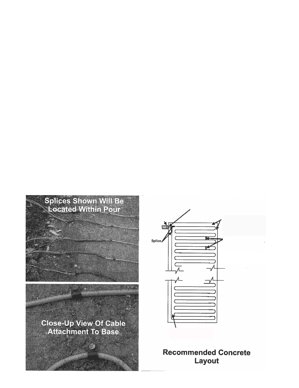
The direction of the cable layout is not important in asphalt or pavers in sand. In concrete it is strongly recommended to lay the cable
across the shorter dimension of the space. (Below Right) If for any reason the concrete cracks, it normally cracks across the shorter
dimension. It is important that the cable finishes at the same point it started, which is usually a junction box. (Lower Right) (The lead
wire can be run underground and into a building through an approved conduit per NEC. If the lead wire must be run in the
heated area, it must be run in conduit). Decided where you are going to start and end each of your cable(s) within the design area.
Start by laying the cable with the splice, making sure the splice (heat shrink) is buried into the pour. We recommend attaching the
cable every 12 - 18 inches to assure no movement while embedding within the pour. Run the cable along the outside edge of the
design area, halt the “on center”spacing (located on the UL flag tag) to the furthest point away from the starting point (See Diagram
below). After the interior edge is down, start to use the full “on center” spacing located on the UL flag tag and lay the cable in a
serpentine fashion in order to fill the design area, ending the cable where it started. It is important to remember to maintain half the “
on center” spacing dimension around the remaining outer edges of the design area. ‘Where multiple cables are being installed (See
Page 4) into one design, follow the layout until only enough cable remains unattached to make the homerun back to the starting
point. Repat as required.
INSTALLATION EXAMPLES
Maintain Recommended Spacing
Between Cables On Home Run
Cold End Leads are to exit
concrete in conduit. do not
place the heating cable nor
the splice inside
conduit
Both ends of the cable have to connect to the
power source (either the control sensor or the
contractor panel)
Maintain 1/2 of the
recommended cable
spacing between the
cable and the walls or
other permanent structure
Cable spacing refers to the
distance between the
parallel runs out of cable
Diameter of return bend
must never be less than 2
inches