Dimensions, Boiler micro-bubbles, Cavitation and micro-bubbles – Infloor Air Separators 31080-31088 User Manual
Page 2
Code
A
B
D
E
F
G
Weight (lb)
2”
13
3/4
”
14
3/4
”
19
15/16
”
6
5/8
”
1"
33.1
2
1/2
”
13
3/4
”
14
3/4
”
19
15/16
”
6
5/8
”
1"
34.2
3”
18
3/8
”
17
1/8
”
23
7/16
”
8
5/8
”
1"
61.7
4”
18
1/2
”
17
1/8
”
23
7/16
”
8
5/8
”
1"
66.1
5”
25
21
7/16
”
30
1/2
”
12
3/4
”
1"
105.8
6”
25
21
7/16
”
30
1/2
”
12
3/4
”
1"
116.8
Size
2”
2
1/2
”
3”
4”
5”
6”
Cap. (gal)
1.8
1.8
4.8
4.8
13.7
13.7
M
ax
am
oun
t
in
g
al
lo
ns
o
f
di
s
s
ol
v
ed
ai
r
p
er
100
gal
lo
ns
o
f
w
a
te
r
A
A
D
A
E
A
C
D
A
A
D
E
P
re
ss
ur
e
A
D
E
Ve
loc
it
y
Dimensions
C
C
F
F
F
B
B
Code
A
B
C
D
E
F
Weight
(lb)
31080
3/4”
3
1/16
”
2
3/16
”
5
5/8
”
6
7/8
”
1/2”
2.0
31080
3/4”
3
1/16
”
2
3/16
”
5
5/8
”
6
7/8
”
1/2”
2.0
G
B
E
B
Code
A
B
C
D
E
Weight
(lb)
31080
3/4”
4
5/16
”
5
3/4
”
7
1/2
”
1/2”
3.7
31082
1”
4
5/16
”
5
3/4
”
7
1/2
”
1/2”
3.7
31084
1
1/4
”
4
7/8
”
6
9/16
”
8
1/4
”
1/2”
4.9
31087
1
1/2
”
4
7/8
”
6
9/16
”
8
1/4
”
1/2”
4.9
31088
2”
5
1/8
”
6
5/16
”
8
1/4
”
1/2”
4.9
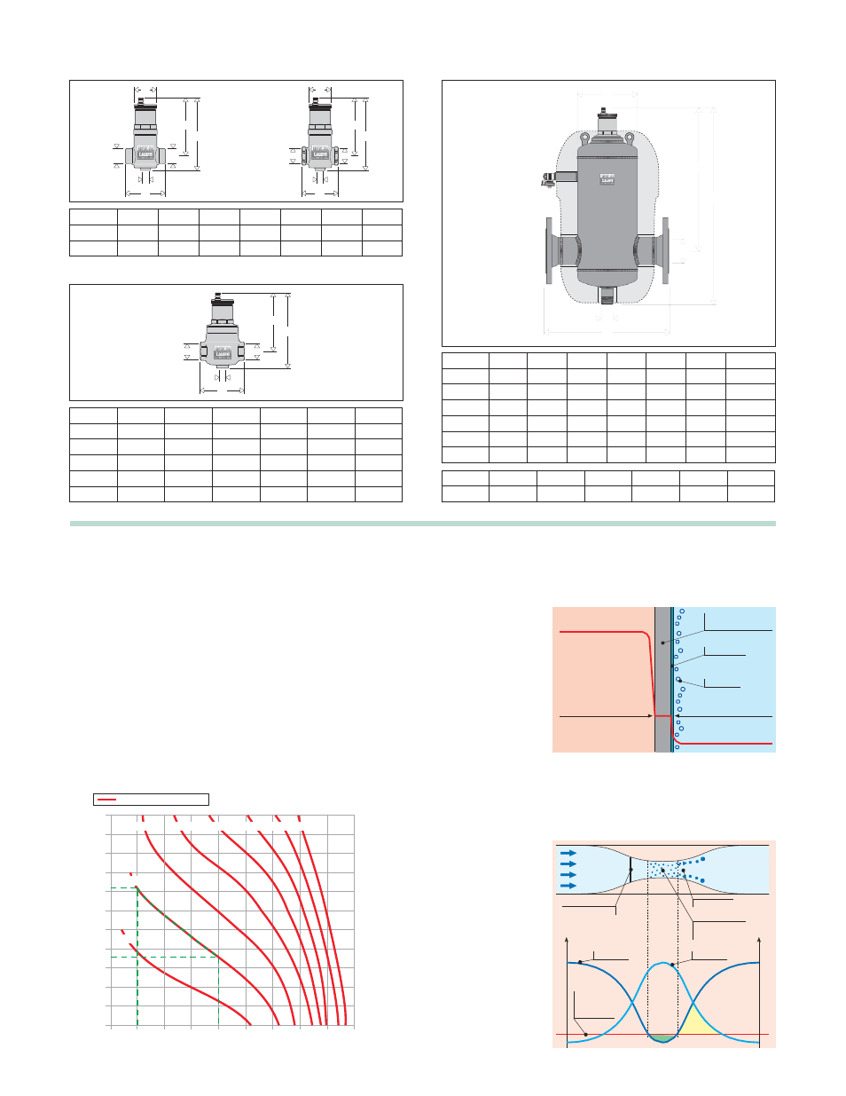
The process of air formation
The amount of air which can remain dissolved in a water solution is
a function of pressure and temperature.
This relationship is governed by Henry’s Law and the graph below
Boiler micro-bubbles
Micro-bubbles are formed continuously on the surface separating
the water from the combustion chamber due to the fluid temperature.
This air, carried by
allows the physical phenomenon of the air content release of the
fluid to be quantified.
As an example, at a constant absolute pressure of 30 psi (2 bar), if
the water is heated from 65°F (18°C) to 170°F (75°C), the amount
the water, collects
in the critical points
of the circuit from
where it must be
Flame temperature
1000
°C
Combustion chamber
wall
Boundary layer
of air released by the solution is equal to 1.8 gallons of air per 100
gallons of water.
According to this law it can be seen that the amount of air released
removed.
Some of this air is
reabsorbed in the
FLAME
WATER
Micro-bubbles
increases with temperature rise and pressure reduction. The air
comes in the form of micro-bubbles of diameters in the order of
tenths of a millimetre.
In heating and cooling systems there are specific points where this
process of formation of micro-bubbles takes place continuously: in
the boiler and in any device which operates under conditions of
cavitation.
presence of colder
surfaces.
Wall temperature
160
°C
Boundary layer
temperature 156
°C
Average water
temperature 70
°C
5.5
5.0
4.5
4.0
3.5
Absolute pressure
45 psi
60 psi
75 psi
90 psi 105 psi 120 psi
30 psi
Cavitation and micro-bubbles
Micro-bubbles develop where the fluid velocity is very high with the
corresponding reduction in pressure.These points are typically the
pump impeller and
the regulating valve
seating. These air
and vapour
micro-bubbles, the
3.0
2.5
2.0
15 psi
formation of which
is enhanced in
the case of non
de-aerated water,
Seat-obturator
distance
Implosions
Cavitation
micro-bubbles
1.5
1.0
0.5
may subsequently
implode due to the
c a v i t a t i o n
phenomenon.
Pressure
Velocity
Fluid vapour
pressure
0
32 65
100
135 170 205 240 275 310 345
Water temperature (
°F)