Hydronic characteristics, Caleffi, Specification summaries – Infloor Air Separators 31080-31088 User Manual
Page 4: Hydronic characteristics installation
THREADED
FLANGED
Size
3/4” C
3/4”
1”
1 1/4”
1 1/2”
2”
2”
2 1/2”
3”
4”
5”
6”
Cv
14
19
21
43
51
78
86
179
211
345
520
809
2
2
.5
3
3
.5
4
4
.5
5
6
7
8
9
10
12
14
16
18
20
25
30
35
40
45
50
60
70
80
90
100
120
140
160
180
200
250
300
350
400
450
500
600
700
800
900
1000
0,
5
0
,6
0
,7
0
,8
0
,9
1
1
,2
1
,4
1
,6
1
,8
2
2
,5
3
3
,5
4
4
,5
5
6
7
8
9
10
12
14
16
18
20
25
30
35
40
45
50
60
70
80
90
100
120
140
160
180
200
3/
4"
C
3/
4"
1"
1
1/
4"
1
1/
2"
2”
D
N
50
D
N
65
D
N
80
D
N
100
D
N
125
D
N
150
G
(m
3
/h)
(gpm
)
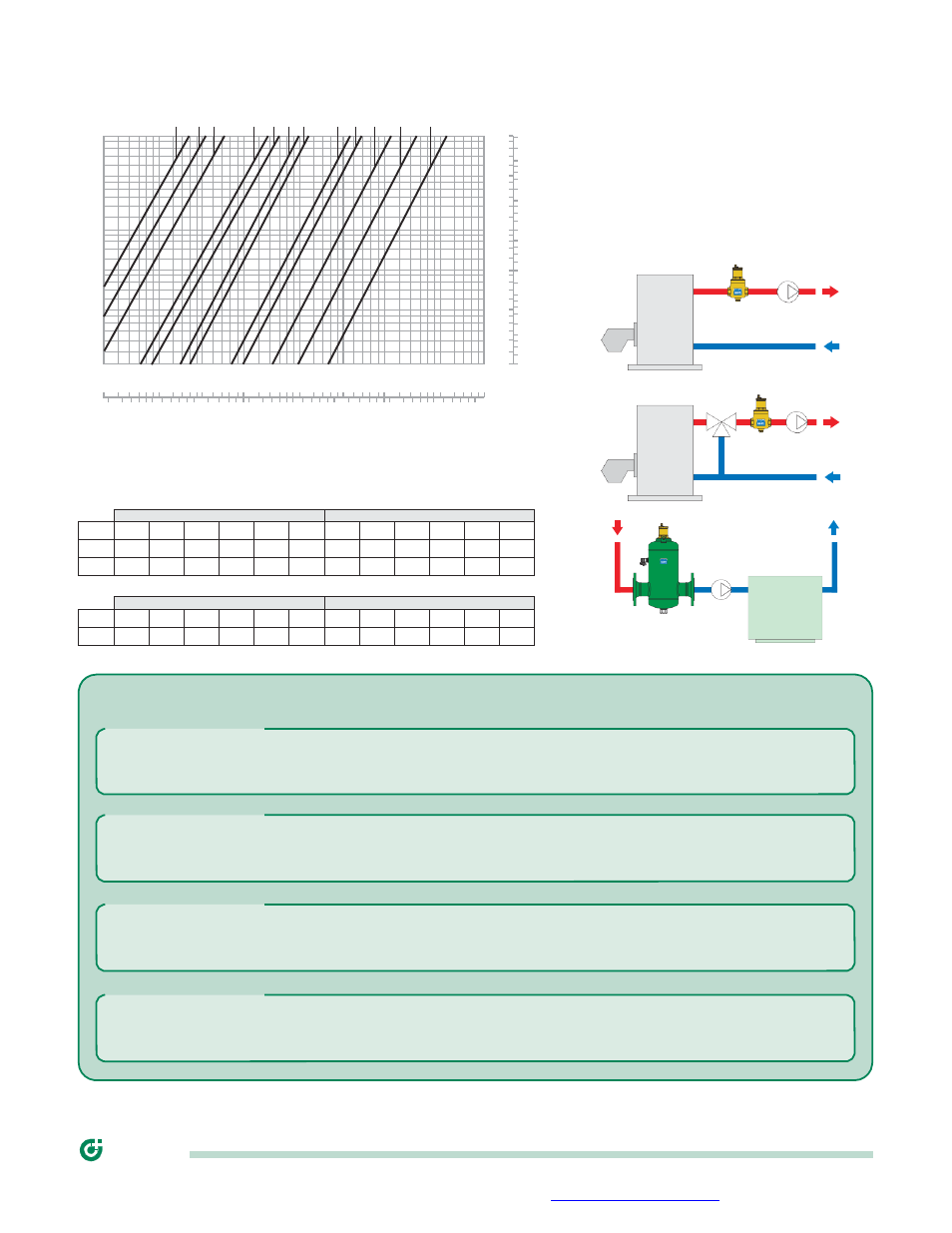
Hydronic characteristics
Installation
∆P (ft of water)
(ft of water) (kPa)
DISCAL units may be used in both heating and
cooling systems, to ensure the progressive removal of
1
0.9
0.8
0.7
0.6
0.5
0.45
0.4
0.35
0.3
0.25
0.2
0.18
0.16
0.14
0.12
0.1
0.09
0.08
0.07
0.06
0.05
0.045
0.04
0.035
0.03
0.025
0.02
1
0.9
0.8
0.7
0.6
0.5
0.45
0.4
0.35
0.3
0.25
0.2
0.18
0.16
0.14
0.12
0.1
0.09
0.08
0.07
0.06
0.05
0.045
0.04
0.035
0.03
0.025
0.02
3
2.5
2
1.8
1.6
1.4
1.2
1
0.9
0.8
0.7
0.6
0.5
0.45
0.4
0.35
0.3
0.25
0.2
0.18
0.16
0.14
0.12
0.1
0.09
0.08
0.07
0.06
air which is continuously formed. The units should
preferably be installed after the boiler and on the
pump suction side, as these are the points where the
formation of micro-bubbles is greatest. DISCAL air
separators must be installed vertically. In installation
conditions where inspection is not possible, it is
recommended that the venting valve cap is replaced
by a Caleffi Code nr. 59681 hygroscopic safety vent.
The maximum fluid velocity recommended at the unit connections is
~
4.2 f/s.
The following table shows the maximum flow rates to comply with this
condition.
THREADED
FLANGED
Size
3/4” C
3/4”
1”
1 1/4”
1 1/2”
2”
2”
2 1/2”
3”
4”
5”
6”
gpm
6
8
10
15
24
36
38
65
95
150
260
380
m
3
/h
1.36
1.81
2.11
3.47
5.42
8.20
8.47
14.32
21.69
33.89
58.8
86.2
CHILLER
SPECIFICATION SUMMARIES
DISCAL Series
Air separator. Connections 3/4" F threads or 3/4” sweat. Bottom 1/2” F. Brass body. EPDM seal. Internal mesh
element of stainless steel, removable for cleaning operations. Maximum working pressure, 150 psi (10 bar).
Temperature range 32 to 250
°F (0 to 120°C). Glycol maximum 50%.
DISCAL Series
Air separator. Threaded connections 3/4" (from 3/4" to 2") F x F. Bottom connection 1/2" F for drain cock. Brass
body. EPDM seal. Internal mesh element of stainless steel, removable for cleaning operations. Maximum working
pressure, 150 psi (10 bar). Temperature range 32 to 250
°F (0 to 120°C). Glycol maximum 50%.
DISCAL Series
Air separator without insulation, complete of drain cock. Flanged 150 CLASS ANSI connections from 2” to 6”.
Body of epoxy resin painted steel. EPDM seal. Internal mesh element of stainless steel. Maximum working
pressure, 150 psi (10 bar). Temperature range 32 to 250
°F (0 to 120°C). Glycol maximum 50%.
DISCAL Series
Air separator complete with insulation and drain cock. Flanged 150 CLASS ANSI connections from 2” to 6”. Body
of epoxy resin painted steel. EPDM seal. Internal mesh element of stainless steel. Maximum working pressure,
150 psi (10 bar). Temperature range 32 to 220
°F (0 to 105°C). Glycol maximum 50%.
We reserve the right to change our products and their relevant technical data, contained in this publication, at any time and without prior notice.
CALEFFI
Infloor Sales and Service, 503 Gregg Drive, P.O. Box 4945, Buena Vista CO 81211 /TEL. 719.395.3400 · FAX 719.395.3555
·