Operation, On/off and gfci, Startup wizard – Infloor Thermostat 29050 V2 User Manual
Page 2: Wire connections, Mounting the control, Overview of features and display
On/Off and GFCI
On/Off and Reset
Pressing will turn the thermostat on or off. This also Resets
the thermostat to clear an error or GFCI fault. See “GFCI Testing” and
“Troubleshooting”.
GFCI Testing
The GFCI (Ground Fault Circuit Interrupter) in this control must be tested when
installation is finished and once each month.
• Make sure the control shows it is Heating. This may require temporarily
increasing the setpoint temperature.
• Press the button. GFCI TRIP should be indicated on the control.
There will also be a click sound, indicating power has been removed from
the floor heating system. If either of these indications fail, turn off the
thermostat and replace it. Do not continue to use.
• To reset the GFCI TRIP, press
on/off
off and back on.
Startup Wizard
This thermostat comes with a “wizard” to help the user through basic setup.
• When first powered up, or upon resetting the factory defaults, the display
will ask to set the year. Adjust the year by pressing
or
and press
OK
.
• Select the month and press
OK
.
• Select the day and press
OK
.
• Set the hour and minutes (format is 12-hour clock but this can be changed
to a 24-hour clock). See Changing Settings Section.
• Select the sensing method (Floor or Air). Default is Floor. See cautions
before using the Air Sensing method. See Changing Settings Section.
• Select a program schedule. The default is called “Normal Day” where it
makes the floor warmer during morning and evening hours. Any of the
schedules can be customized to fit your needs.
• Press
OK
and the thermostat will begin working automatically.
NORMAL DAY
Cycle
WAKE
LEAVE
RETURN
SLEEP
Monday –
Friday
6:00 AM
(6:00)
8:00 AM
(8:00)
5:00 PM
(17:00)
10:00 PM
(22:00)
82 F (27.8 C) 74 F (23.3 C) 82 F (27.8 C) 74 F (23.3 C)
Saturday
7:00 AM
(7:00)
9:00 AM
(9:00)
5:00 PM
(17:00)
11:00 PM
(23:00)
82 F (27.8 C) 74 F (23.3 C) 82 F (27.8 C) 74 F (23.3 C)
Sunday
7:00 AM
(7:00)
9:00 AM
(9:00)
5:00 PM
(17:00)
11:00 PM
(23:00)
82 F (27.8 C) 74 F (23.3 C) 82 F (27.8 C) 74 F (23.3 C)
NOTE: Air Sensing mode default temperatures are 70F and 62F.
WARM ALL NIGHT
Cycle
WAKE
LEAVE
RETURN
SLEEP
Monday –
Friday
--
8:00 AM (8:00) 5:00 PM (17:00)
--
--
74 F (23.3 C)
82 F (27.8 C)
--
Saturday
--
9:00 AM (9:00) 5:00 PM (17:00)
--
--
74 F (23.3 C)
82 F (27.8 C)
--
Sunday
--
9:00 AM (9:00) 5:00 PM (17:00)
--
--
74 F (23.3 C)
82 F (27.8 C)
--
NOTE: Air Sensing mode default temperatures are 70F and 62F.
HOME DURING DAY
Cycle
WAKE
LEAVE RETURN
SLEEP
Monday –
Friday
6:00 AM (6:00)
--
--
10:00 PM (22:00)
82 F (27.8 C)
--
--
74 F (23.3 C)
Saturday
7:00 AM (7:00)
--
--
11:00 PM (23:00)
82 F (27.8 C)
--
--
74 F (23.3 C)
Sunday
7:00 AM (7:00)
--
--
11:00 PM (23:00)
82 F (27.8 C)
--
--
74 F (23.3 C)
NOTE: Air Sensing mode default temperatures are 70F and 62F.
Wire Connections
Match and connect the two wires marked “LINE1(L)” and “LINE2(N)” to the
house power supply wires using the wire nuts provided. Gently tug on the wires
to make sure they are secure, otherwise a wire could come loose and cause
failure. For added security, overwrap the connections with electrical tape.
Match and connect the two wires marked “LOAD1” and “LOAD2” to the power
lead wires from the floor heating system. Secure these wire connections the
same way with the appropriate size wire nut for the number of wire connected.
CAUTION: Make sure the house power supply voltage matches the voltage
rating of the floor heating system. Do not apply 240 VAC to a 120 VAC rated
system. Connecting the wrong voltage may cause overheating and damage
to the system, the control, floor coverings, etc.
Connect the house ground wire to the ground wire(s) from the floor heating
system. If the electrical box is metal, a short length of wire must be secured to
the electrical box from this ground connection.
Insert the ends of the floor sensor wire into the terminals marked “SENSOR” and
snug the screws. It does not matter which wire goes into which terminal
Infloor Relay 29053
version 2 only (Optional)
Read and follow the instructions provided with the 29053 Version 2.
Pull 18 AWG to 24 AWG 2-conductor shielded wire through the wall from the
Infloor Relay location to this control location. This wire may be up 100 feet (30
m) in length. Strip the wire ends 1/8” to 3/16” (3 mm to 4.5 mm) long. If the
ends are stripped longer than this they may short-circuit.
Connect the wire ends into the “BUS” A and B terminals. Make sure the wire in
“A” terminal is connected to an “A” terminal in the Infloor Relay.
Mounting the Control
Carefully press the wires back into the electrical box. Do not use the control to
push them in, as this may cause connections to loosen and possible failure.
Loosen the screw and remove the front module from the power module. Secure
the power module into the electrical box with the mounting screws provided.
Snap the front module onto the power module and tighten the screw. Press the
Screw Cover in place to cover screw.
Operation
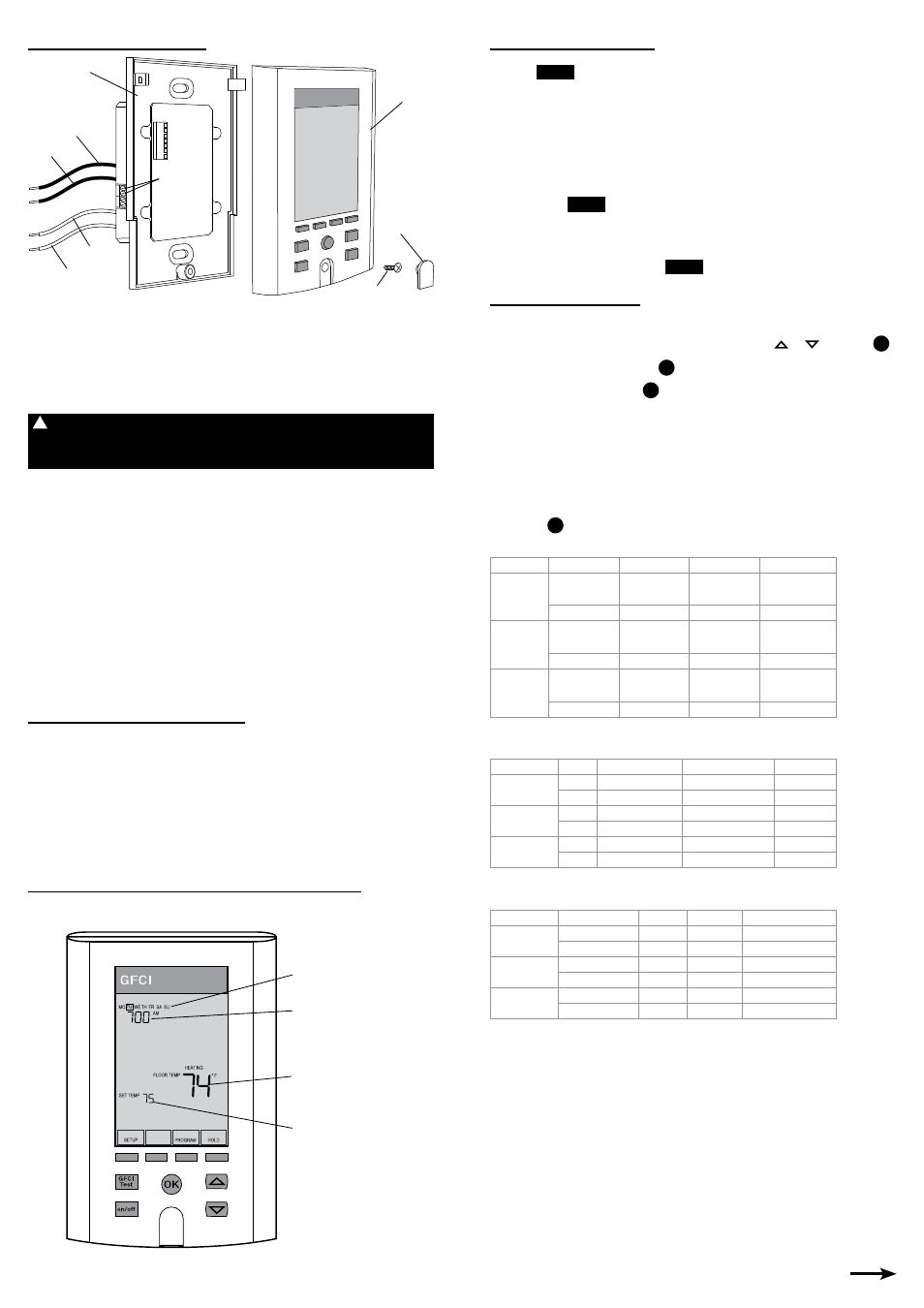
Overview of Features and Display
Press a button if the display is dark. This wakes the display backlight.
on/off
GFCI
Test
Setpoint temperature
Floor temperature
Day
Time
Screw Cover
Cover Screw
Front Module
Load 1
Line 1
Line 2
Load 2
Floor Sensor
Connection
Power Module
!