English, 10 shielding gas, 11 gas flow regulator – Kemppi DC 3500W User Manual
Page 9
9901 / 1916110E / 9
English
Welding current
range AC
Elec-
trode
Gas nozzle
Gas
flow
rate
min
min
max
WC20
Argon
A
A
A
ø mm number
ø mm
l / min
15
25
90
1,6
4/5/6
6,5/8,0/9,5
6...7
20
30
150
2,4
6/7
9,5/11,0
7...8
30
45
200
3,2
7/8/10
11,0/12,5/16
8...10
40
60
350
4,0
10/11
16/17,5
10...12
56
55
57
56
53
P1
P2
51
52
54
The table is only given as a guide.
The table and the panel scale are based on the use of
WC20 (grey). When using pure wolfram electrode
(green) the tip rounds off slightly.
2.10 Shielding gas
Use as the shielding gas argon or other gas which is
suitable for TIG welding. The flow rate of the gas is
defined by the welding current and the size of the elec-
trode. The table above shows the flow rate recommend-
ed.
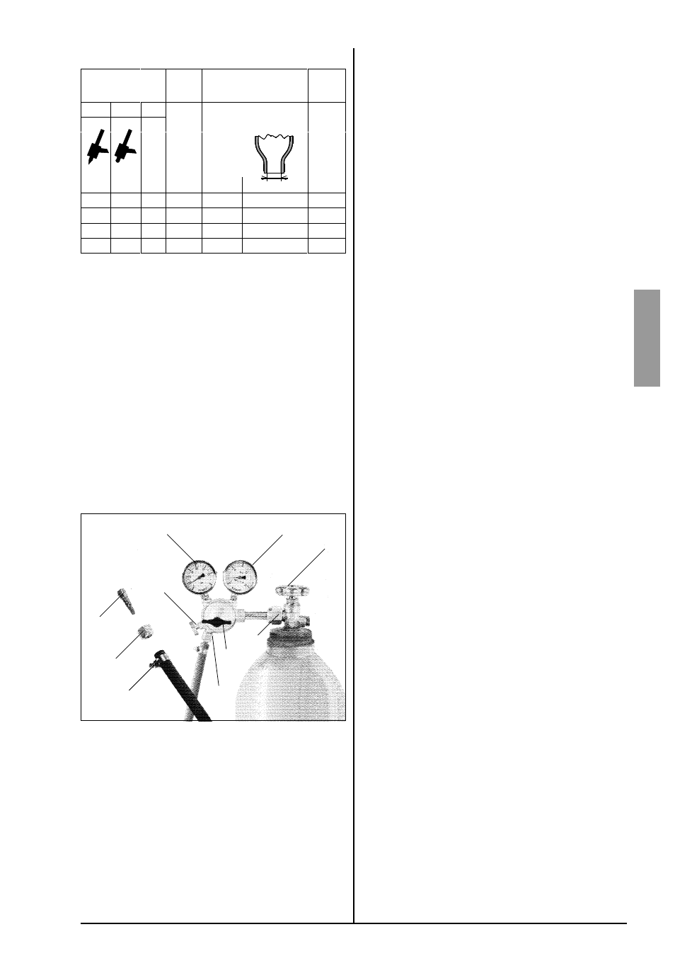
2.11 Gas flow regulator
Gas flow regulator should be suitable for shielding gas
used by you. The regulator being in your use might be
different from the one in picture, however, following gen-
eral instructions are valid for all pressure regulators.
Before mounting of flow regulator
Step aside, open cylinder valve (1) somewhat for a
moment, in this way you can blow out any dirt that
may be in the valve of bottle.
Screw the press regulation screw (2) of regulator
outwards so long that no spring pressure can be
felt (screw is turning freely).
Close needle valve (3) if there is one in regulator.
Connect regulator onto valve of bottle
Tighten connecting nut (4) preferably with a wrench.
Put hose spindle (5) of regulator with jacket nuts
(6) onto gas hose, connection should be ensured
with hose clamp (7).
Connect hose onto regulator and machine, tighten
jacket nuts.
Open valve of bottle slowly
Pressure meter (P1) shows pressure of bottle. Nev-
er use up all the gas in the bottle, send the bottle
for filling up when the bottle pressure still is 2 bar.
Open needle valve if there is one in regulator.
Screw regulation screw (2) inwards until hose pres-
sure meter (P2) shows flow (or pressure) required.
By regulation of flow amount the machine has to
be in operation and the gun switch should be
pressed on at the same time.
Close valve of bottle always after having stopped
welding
If the machine will be unused for a longer time, you
should also unscrew pressure regulation screw (2).