La Crosse Technology WS-2510 User Manual
Page 8
8
electronics. The upper part of the housing can now be placed so that the solar cell is on the same side as the magnet,
with the electronic part directly opposite it, with the three catches fitting neatly into the holding devices in the lower part.
Finally turn the upper part gently anti-clockwise until it securely slots into holding devices of the lower part.
The rain sensor is then ready for operation. As a test pour a little water gently into the funnel. The amount collected will
then be converted in the base unit to inches, litres/m
2
or mm and displayed.
2.3.3. Brightness
sensor
WS-2510-19
The brightness sensor detects the brightness at the current location in a range between 0 and 200000 lux. It is powered
by an integral solar cell and also has a fixed address. To mount the sensor, the plastic point is inserted on one side of the
aluminum tube supplied and the sensor is fitted on the other side of the tube. The sensor can now be inserted into the
ground. Depending on the firmness of the ground, the earth spike should be inserted so that the sensor is about 8-12
inches (20-30 cm) above the ground to avoid it becoming dirty due to mud splashing up onto it.
The sensor should be turned so that the solar cell points to the south. The location must be free from shadows and the
sun able to shine directly onto the measuring head. The sensor must be mounted vertically with the measuring head at
the top.
2.3.4 Addressing of the temperature/humidity sensors WS-2510-22, WS-2510-25, and WS-2510-27
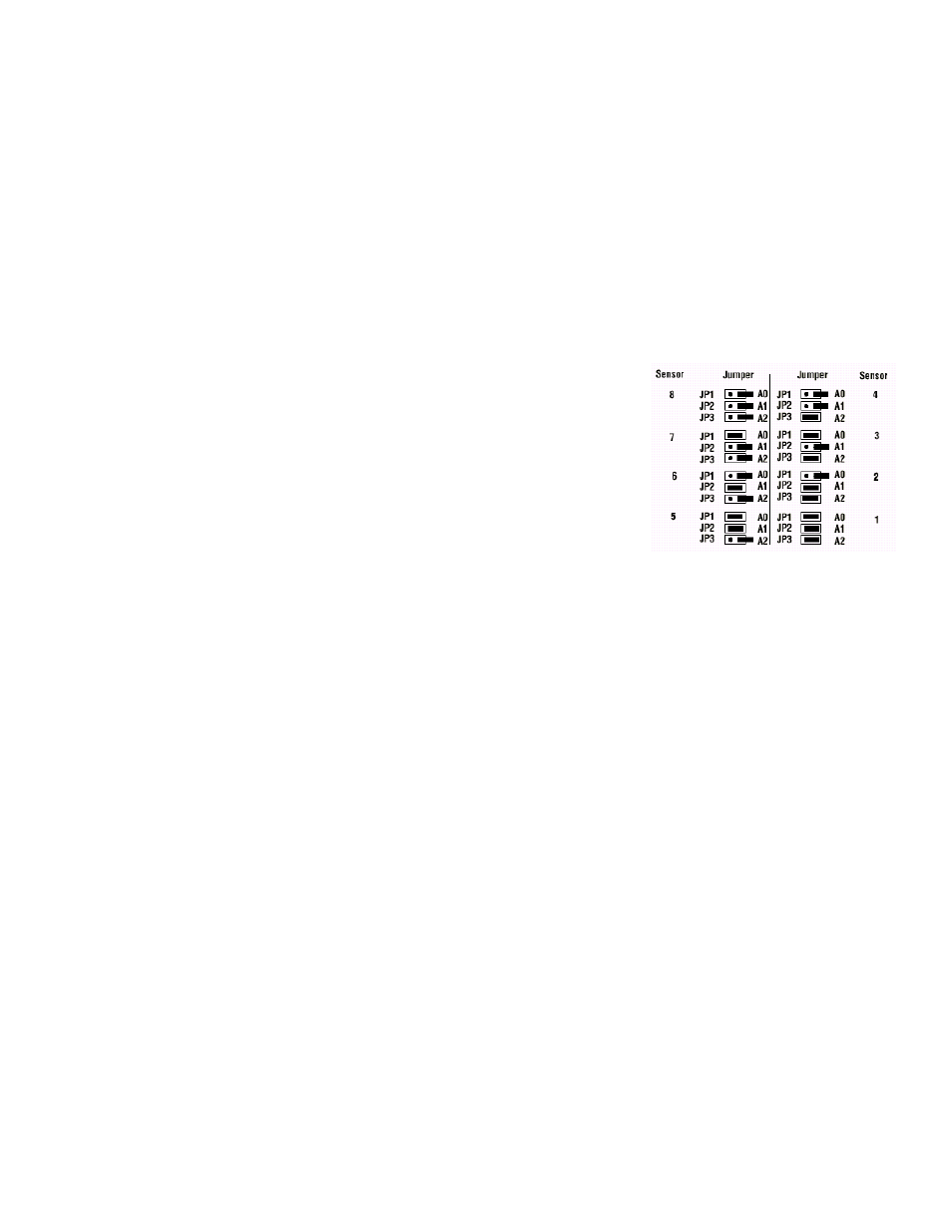
The outdoor sensor concept enables the concurrent deployment of up to eight
outdoor sensors, whose data can be selected by the user to appear in the top right
hand field of the display. Each sensor in the system is assigned a sensor address,
which enables the receiver to integrate the sensor into the total system without any
problems. Each sensor delivered is set to sensor 1. The programmable allocation is
clear from the diagram.
The addressing can be self-generated by means of coding bridges on the
conductive side of the sensor board. To do this on the WS-2510-25 unscrew the
protective bell housing on the sensor housing and open the housing by removing
the screws on the rear.
The WS-2510-22/27 types only require the housing rear wall to be unscrewed.
The coding bridges must then be set according to the address table.
2.3.5 WS-2510-22 temperature/humidity sensor
The WS-2510-22 contains a temperature and a humidity sensor. This sensor is freely addressable for displaying within
the display field at the top right of the display (see display overview on page 4). The addressing can be set individually
according to section 2.3.4. Since it is exclusively battery operated this sensor is suitable for use in (dark) inner rooms such
as a garage, a wine cellar or loft.
2.3.6 WS-2510-27
temperature/humidity
sensor
The WS-2510-27 requires two AA alkaline batteries for operation. It enables the recording of garden, pond or ground
temperatures or similar by means of an encapsulated temperature sensor, remotely connected to the electronics by a 10
foot (3 m) cable.
This sensor can also be freely addressed for displaying within the display field at the top of the display (see display
overview on page 4). The addressing can be set individually according to section 2.3.4.
Now you can mount or position the electronics housing at the required location and place the temperature sensor on or in
the required object.
2.3.7 WS-2510-25 temperature/humidity outdoor sensor
The WS-2510-25 outdoor sensor enables the transmission of the temperature and humidity at the sensor location.
This sensor can also be freely addressed for displaying within the display field at the top of the display (see display
overview on page 4). All WS-2510-25 sensors are set at the factory to sensor 1. In accordance with section
2.3.4.individual addressing is also possible.
The sensor should be mounted on the north or west side as meteorological temperature recording normally takes place
“in shadow ”. It can also be placed at other locations if desired. You only need to make sure that the solar cell that
provides the sensor with power is permanently aligned towards the light. The sensor must not be shaded by dense
obstructions such as leaves, etc., which could impair the power supply from the solar cell. However, the solar cell does
not have to be exposed to direct sunlight. The ambient brightness is sufficient to charge the battery.
A possible location for installation is under the eaves of the roof.
The sensor is designed for wall and mast mounting and should be mounted as follows: Attach the sensor wall bracket
either exactly vertically to a wall using the four screws, or to a mast using the securing clamp provided.
Position the sensor on the wall bracket and screw the two parts together using the screw provided.
When doing this, the large protective bell housing must be at the top and the solar cell must be pointing towards the light.
During the hours of darkness and periods of bad weather with relatively little sunlight an internal battery system, which is
charged by the solar cell during periods of sunshine, provides the power for the sensor.