Legrand WKD Pro Series System User Manual
Page 2
2
JUNCTION BOX AND WALKERDUCT INSTALLATION LAYOUT:
1.
Secure bench marks at convenient locations on walls or columns wherever the underfloor duct system is to be
installed. This will help establish the level of the finished concrete floor.
2.
Obtain the location of the first duct run from the plans.
3.
Stretch a base line, at finished floor level, that corresponds with the center of the duct run.
4.
In the middle, and at right angles to the line created in Step 3, stretch another line.
5.
These two lines should be used as measuring points for laying out the horizontal and vertical runs of duct.
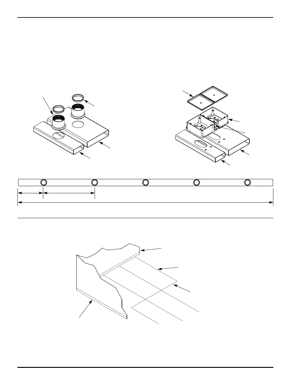
2" IPS PRESETS SHOWN
12" [305mm]
24" [610mm]
10' [3m]
Exterior Wall
STEP 1
STEP 3
First Horizontal
Run of Duct
STEP 4
Vertical Run of Duct
2" IPS DUCT
PRO SERIES DUCT
2" IPS Preset
#4 Duct
#2 Duct
#2 Duct
Mudcap
#4 Duct
Alignment Clip
Pro Series Preset
Mudcap
DUCT:
1. Duct is manufactured in two sizes and in two styles. 2" IPS round preset and Pro Series rectangular preset duct.
a. No. 2 Duct is 3 1/8" wide x 1 1/4" deep [79mm x 32mm] with a cross sectional area of 3.34 sq. in. [2155 sq. mm].
b. No. 4 Duct is 6 1/2" wide x 1 1/2" deep [165mm x 38mm] with a cross sectional area of 8.72 sq. in. [5626 sq. mm].
2. The largest conductor to be installed in either duct shall be 1/0.
3.
Preset duct for distribution runs is standard 10' [3m] length with five presets spaced 12" [305mm] from each end and
on 24" [610mm] centers. (Shown below).
a. Other insert spacing is available.
b. Blank duct (duct without preset inserts) is available for home runs, main system feeds and afterset applications.