Junction box, Jr/js and hr/hs series – Legrand WKD Pro Series System User Manual
Page 9
9
JUNCTION BOX
JR/JS and HR/HS Series
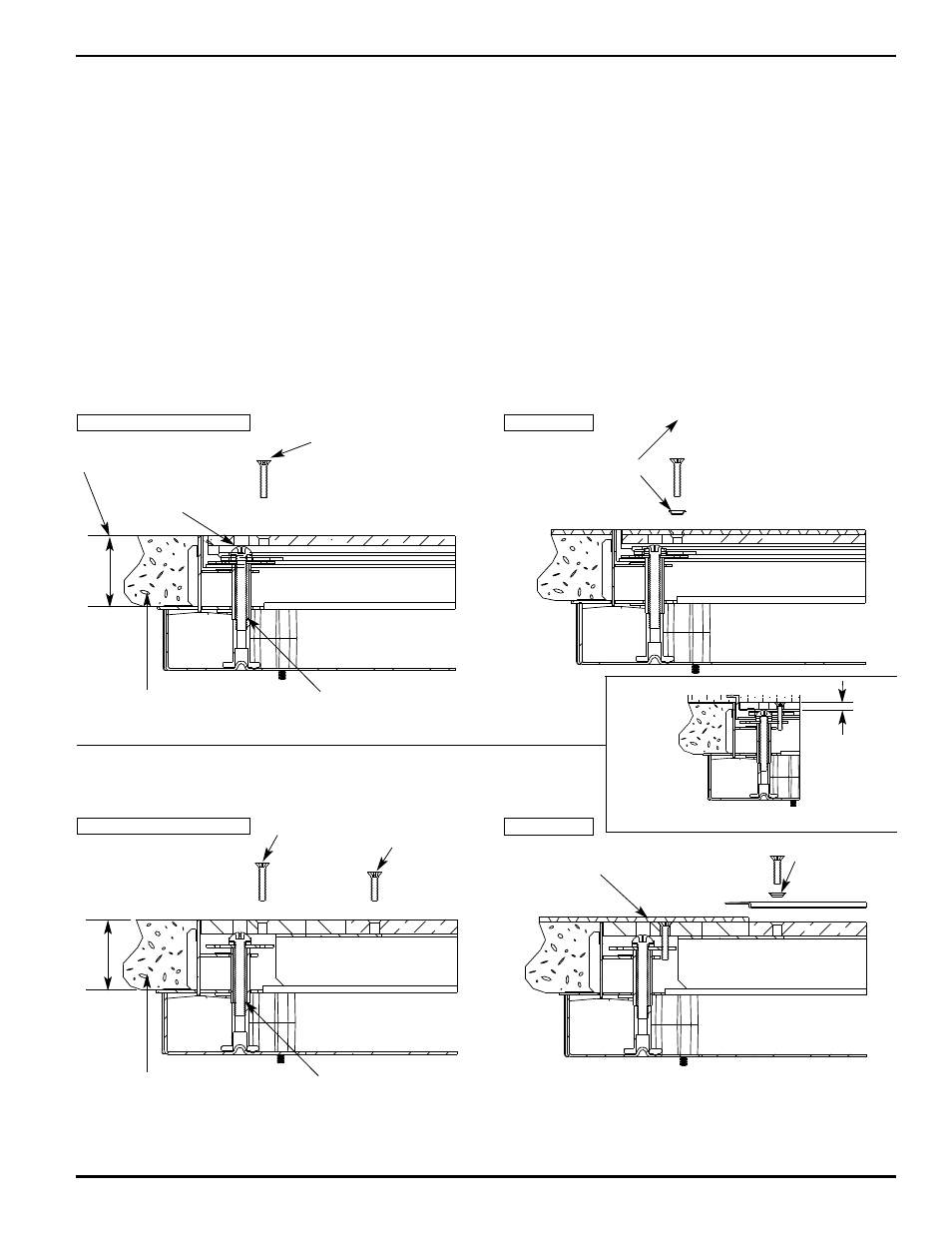
SQUARE COVER PLATE
Junction Box Detail (JS/HS)
ROUND COVER PLATE
Junction Box Detail (JR/HR)
Cover Hold-Down
Screw #10-24 x 1"
[25mm] F.H.M.S.
Cover Hold-Down
Screw #10-24 x 1"
[25mm] F.H.M.S.
Cover Hold-Down
Screw #10-24 x 3/4"
[19.1mm] F.H.M.S.
#10 Escutcheon
Order Part #442005
Adjust Cover Plate
up to Meet Tile Finish
1/8" [3.2mm] Spacer
(Remove for Tile Finish)
Optional Carpet Frame Detail
#10 Escutcheon
1" [25mm] Standard. For
Other Heights Order Side
Rail Extension Kits
1" [25mm] Standard. For
Other Heights Order Side
Rail Extension Kits
Grout as Required
to Prevent Tile
from Cracking
Grout as Required
to Prevent Tile
from Cracking
NOTE: For Tile Floor Order Gasket #454038
(supplied in 100 ft. rolls) Order
Escutcheon #442005
Coverplate Adjusting Screw 5/16-18 R.H.M.S. Slotted
Head with Special Washer. (Washer Part #J11060)
1/2" [12.7mm] Max. Upward Adjustment.
Coverplate Adjusting Screw 5/16-18 R.H.M.S. Slotted
Head with Special Washer. (Washer Part #J1106)
1/2" [12.7mm] Max. Upward Adjustment.
Adjust Aluminum
Frame to meet
Tile Finish
Shipping/Carpet Position
Shipping/Carpet Position
Tile Position
Tile Position
1/4"
[6.4mm]
1"
[25mm]
1"
[25mm]
FINAL SYSTEM ADJUSTMENTS- AFTER THE CONCRETE POUR:
Level the Junction Box Cover Plates:
1.
Level all junction box tops to the finished floor level by means of the coverplate adjusting screws. Remove the 10/24 x 1"
[25mm] flat head screws. Just below the large holes in the cover plate are four slotted or phillips 5/16-18 machine screws
with a special washer that accommodates the hold down screw in four locations. These screws have 1/2" [12.7mm]
upward adjustment.
2.
Place a level across the adjusting frame and use the adjusting screws to bring the cover plate up to the finished floor level.
Turning the adjusting screw no more than 1/4 [90°] turn in either direction will locate one of the four tapped holes for the
corner hold down screw.
3.
Once the junction box cover has been leveled, remove the cover plate and check the height of any support studs within the
box so that the cover plate rests on the studs when in place.