Legrand WKD Pro Series System User Manual
Page 4
4
Junction Box
Distance Between Duct Ends
Catalog Number
Within Junction Box
12JS, JR, HS, or HR
7"
[178mm]
14JS, JR, HS, or HR
11 1/8"
[283mm]
222JS, JR, HS, or HR
11 1/8"
[283mm]
224JS, JR, HS, or HR
15 1/4"
[387mm]
3222JS, JR, HS, or HR
15 1/4"
[387mm]
244JS, JR, HS, or HR
18 5/8"
[473mm]
3224JS, JR, HS, or HR
18 5/8"
[473mm]
42222JS, JR, HS, or HR
19 3/8"
[492mm]
3424JS, JR, HS, or HR
22"
[559mm]
3244JS, JR, HS, or HR
22"
[559mm]
522222JS, JR, HS, or HR
23 1/2"
[597mm]
3444JS, JR, HS, or HR
25 3/8"
[645mm]
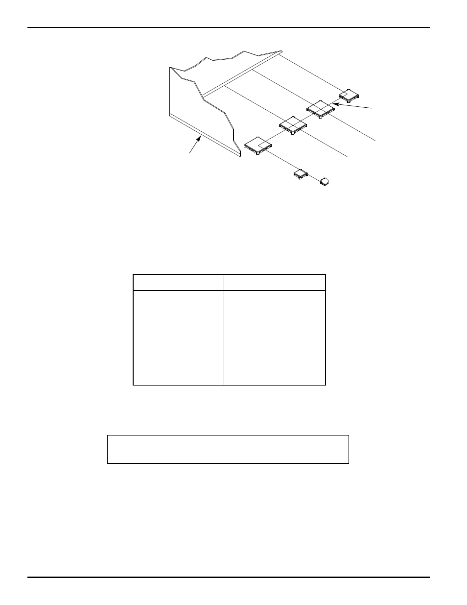
LOCATE JUNCTION BOXES:
Junction boxes are used at intersections of duct runs.
1.
Locate along the horizontal base line the point where junction boxes are to be centered.
2.
Junction boxes must be positioned correctly so that the duct arrangement will conform to the electrical drawings. After the
correct position is established and power and telephone service have been assigned to specific duct runs, the arrow on the
junction box side must be noted. All junction boxes in any interconnecting area must be placed with arrow pointing in
the same direction. This establishes a consistent pattern for all inter-connecting duct runs. When Wiremold/Legrand layout
drawings are provided, the arrows on the installed box must match drawings.
3.
Proceed with other rows of boxes, making sure that centers are lined up vertical and horizontally with the first row of boxes.
See chart above for dimension to allow for duct length between boxes.
Exterior Wall
Center line
CAUTION:
When field cutting duct to length, always butt factory cut end to factory cut end.
Install field cut end at the end of a given run. Maintains proper insert spacing.