Interfacing with external devices via ir interface – Legrand ADWHRM4 adorne Wireless User Manual
Page 9
15
14
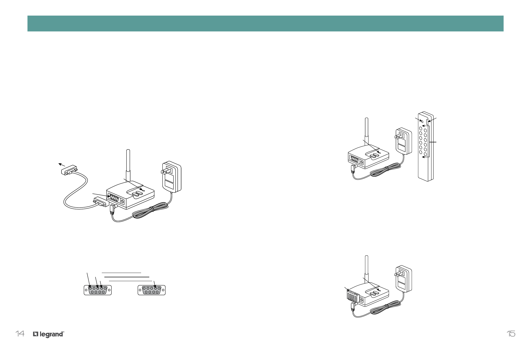
Interfacing with Other Automation Systems via
the RS232 Network Controller
Users can connect their adorne Wireless Lighting with external automation systems for expanded
functionality by using the RS232 Network Controller (MR232-G). The RS232 communicates control
commands to adorne Wireless Lighting components using the controllers of other home systems.
Common applications include:
• Home automation systems
• Home theater systems and whole-house audio/video
• Control of lighting scenes for television or movie viewing using a home theater controller
EXPANDING THE SYSTEM AND INTERFACING WITH OTHER PROGRAMS
EXPANDING THE SYSTEM AND INTERFACING WITH OTHER PROGRAMS
Interfacing with External Devices via IR Interface
In an adorne Wireless Lighting system, the optional IR to RF Interface (MRIR1) is used as a house or room
remote control that works with external IR systems or components to integrate lighting control with other
home automation systems (i.e., whole house audio or home theater systems).
The MRIR1 accepts IR data via an internal IR sensor or an external IR sensor connected to a 3.5mm jack,
and then transmits control signals to the appropriate devices on the adorne Wireless Lighting System
network. The interface is supplied with an external 12V power supply as well as a programming remote.
Interfacing with External Devices via Scene Interfaces
Using the House Scene Interface (MRHC3-G) or Room Scene Interface (MRRC3-G) to connect an adorne
Wireless Lighting Control system with common external devices provides increased functionality. The Scene
Interfaces can be set up to accept either momentary or maintained inputs. The scene assignments are fixed
and cannot be changed. Mode A is typically used with momentary control signals while Mode B is typically
used with maintained control signals.
To Control System
RS232 Port
on MR232
RS232 Port on
automation system
control panel
Network Controller
Status LED
Serial Cable
Serial Port
5=Ground
3=RX
2=TX
Power Supply
5=Ground
3=TX
2=RX
Power Supply
Signal Transmission
Indicicator Light
Scene Select
Switch
Control Buttons
House or Room
Scene Interface
Status LED
Power Supply
House or Room
Scene Interface
Removeable
Terminal Block
Status LED
Power Supply
Signal Transmission
Indicicator Light
Scene Select
Switch
Control Buttons
House or Room
Scene Interface
Status LED
Power Supply
House or Room
Scene Interface
Removeable
Terminal Block
Status LED