2 min and max level, 3 cutoff level, 4 fade curves – LSC Lighting TEKO User Manual
Page 14: Ction, Min and max levels, Fade curves
TEKO Dimmer
Operator Manual V3.0
Manual operation of the “DMX/MEM
Switch” is controlled either “remotely” from a
suitably programmed button on an ePlate or
“locally” from the TEKO touch screen.
Refer to
for details
on how to manually operate the “DMX/MEM
Switch” from the touch screen.
Automatic operation of the “Switch” is
controlled by the presence or absence of a valid
DMX signal from a DMX lighting controller.
When DMX is present it will be automatically
connected to any channels that are set to
“Switch”.
See 5.4.6.2 “DMX/MEM Switch Connect Loss
Action” for details on how to set the “DMX/MEM
Switch” to “Auto Switch” to DMX.
When finished press [Save Setup] [Done]
[Done].
5.3.1.2 MIN AND MAX LEVEL
The “Min Level” attribute sets the level of the
dimmer output when the control signal is set to
zero. Setting this value slightly above zero is
useful to “Pre-Heat” lamp filaments.
“Max Level” sets the level of the dimmer output
when its control signal is set to full.
Press; [Menu] [Dimmer Channels] [Setup] then
use the and buttons to select “Min Level” or
“Max Level”.
When you select a channel(s) (by touching it)
then press [Min Level] or [Max Level], you can
use the keypad that appears to enter the
required percentage level for the selected
channels, then press [Set].
When finished press [Save Setup] [Done]
[Done].
5.3.1.3 CUTOFF LEVEL
The “Cutoff level” attribute is used only with
Fluoro curve selected channels and sets the
lower cutoff level of the dimmer output. This
value can be scaled to suit the turn on/off point
of the connected fluorescent load/s.
Press; [Menu] [Dimmer Channels] [Setup] then
use the and buttons to select “Cut-off
Level”. Select the required Fluoro channels and
then press the “Cut-off Level” button. Note only
channels with fluoro curves applied are
selectable. Use the keypad to program the cut-
off level, then press [Set].
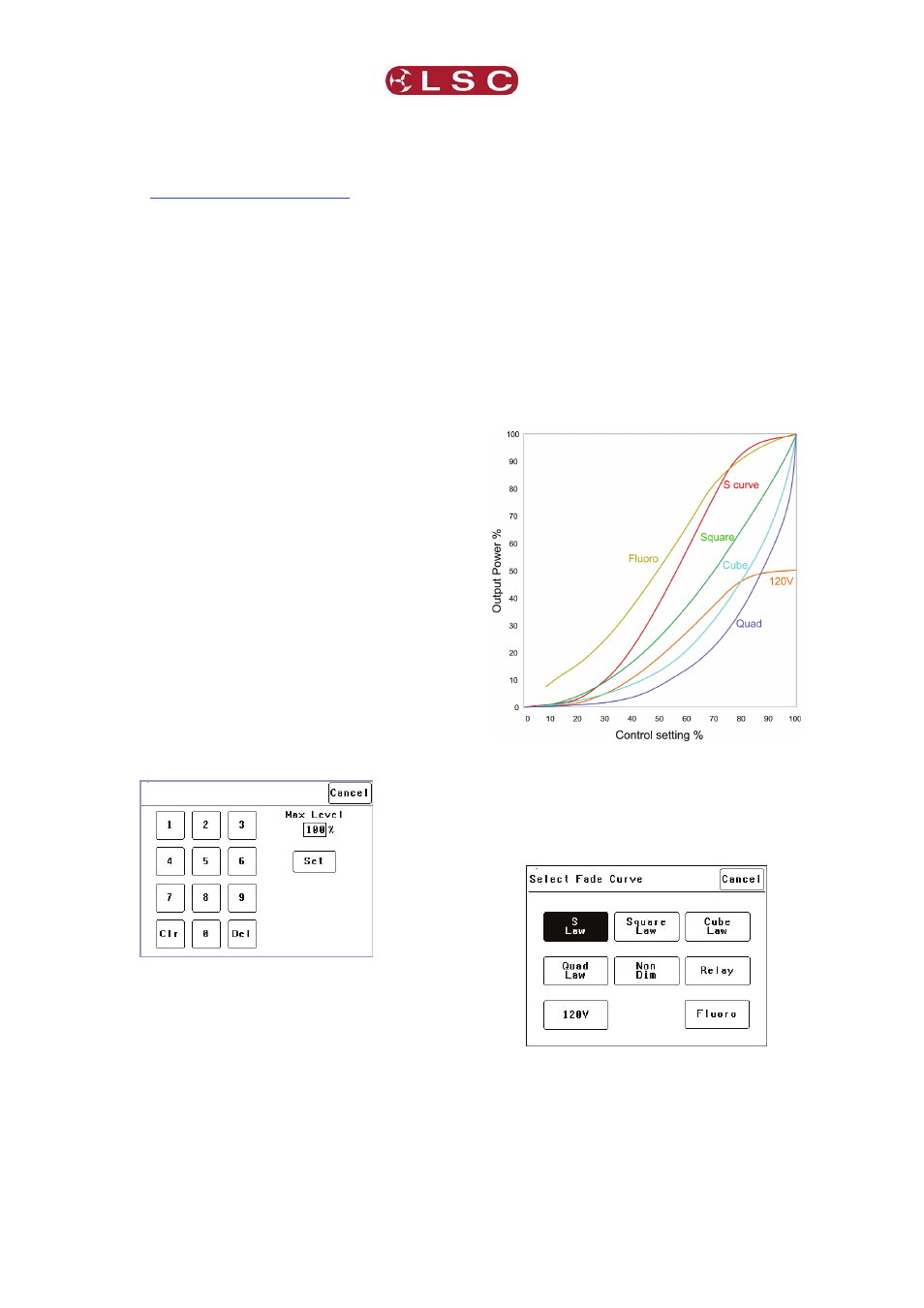
5.3.1.4 FADE CURVES
Fade Curve is the curve or “transfer
characteristic” between input control signal and
dimmer output. The following curves are
available;
S
Law
Square
Law
Cube
Law
Quad
Law
Non
Dim
Relay
120V
Fluoro
Press; [Menu] [Dimmer Channels] [Setup] then
use the and buttons to select “Fade Curve”.
When you select a channel(s) (by touching it)
then press [Fade Curve], you can select the
required curve for the selected channel(s).
“S Law” is the default law and provides a normal
dimmer response.
“Square”, “Cube” and “Quad” laws can be
selected to better match the transfer
characteristic of existing dimmer installations or
to provide the response that you require. Try the
LSC Lighting Systems (Aust) Pty. Ltd
Page
12