9 dmx explained, 1 cable selection, 2 typical dmx installation – LSC Lighting TEKO User Manual
Page 30: Dmx explained
TEKO Dimmer
Operator Manual V3.0
9 DMX Explained
DMX512A is the industry standard for the
transmission of digital control signals between
lighting equipment. It utilises just a single pair of
wires on which is transmitted the level
information for the control of up to 512 DMX
slots (addresses or channels).
When good quality data cables are used,
DMX512 cable runs may be up to 1,000 metres
in length. When several DMX cables are
required to service different locations, DMX512
splitters can be used. Each splitter provides
multiple isolated DMX512 outputs.
The TEKO provides a “DMX Thru” output
allowing you to loop the DMX signal from one
TEKO to the next. The last TEKO in the chain
must have the “DMX Terminate switch” set to
TERM to terminate the line.
9.1 CABLE SELECTION
Do not use unscreened microphone or low
speed data cables for DMX. This can cause
problems in the DMX network. Make sure the
cable conforms to the EIA485 cable
requirements by providing the following
specifications:
Low
capacitance.
One or more twisted pairs.
Foil and braid shielded.
Impedance of 85 -150 Ohms, nominally 120
Ohms.
22AWG gauge for continuous lengths over
300 metres.
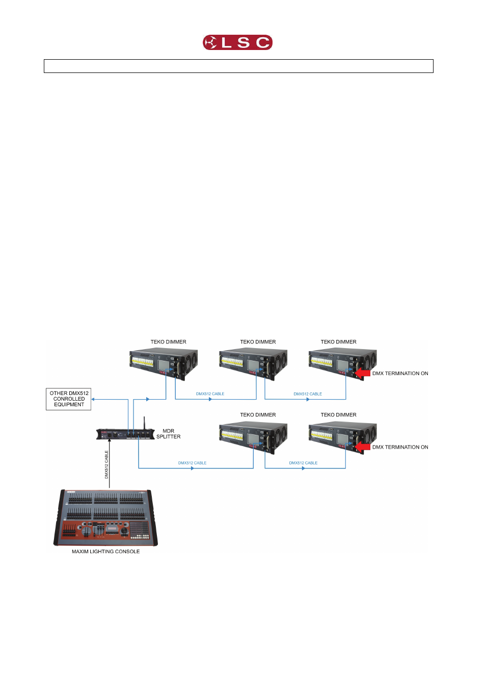
9.2 TYPICAL DMX INSTALLATION
In the diagram below the DMX signal from the
controlling console is connected to a MDR
splitter which provides multiple isolated DMX
outputs. The output cables can then be run to
various locations where dimmers and other
equipment are installed. The end of each DMX
cable must be terminated to prevent the signal
reflecting back up the line and causing possible
errors. In the event of a fault on one of the
cables, the other outputs from the MDR splitter
will not be affected.
LSC Lighting Systems (Aust) Pty. Ltd
Page
28