4 clear patch, 5 view levels, 6 connect loss action – LSC Lighting TEKO User Manual
Page 17: Connect loss action
TEKO Dimmer
Operator Manual V3.0
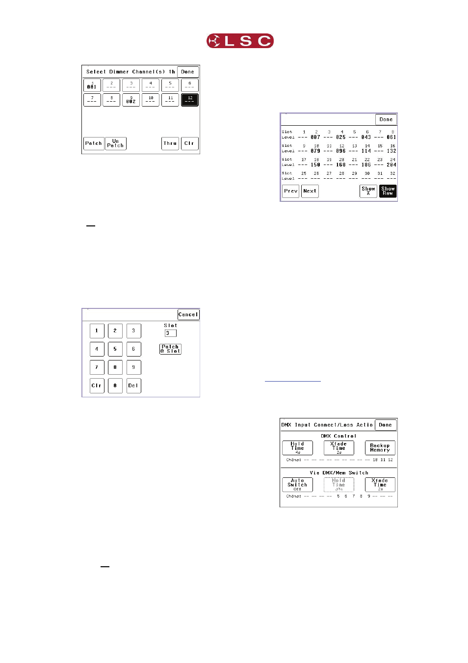
To select a channel, press that channel number.
You can add further channels to your selection
by pressing their channel numbers.
To deselect a channel, press it again.
To select a range of channels, press a channel,
then [Thru] then another channel.
To clear all selections, press [Clr].
In the example above, dimmer 1 is patched to
DMX slot 1 and dimmer 9 is patched to DMX slot
2. Dimmer 12 is currently selected (white text on
black background) ready to be patched.
To make a patch, select the dimmer channel(s)
as described above then press [Patch].
Type in the DMX slot number then press;
[Patch @ Slot].
All of the selected dimmer channels are patched
to the selected DMX slot number.
Select other dimmers and patch them as
required.
To Un-patch a dimmer(s) select the dimmer(s)
then press [UnPatch].
When all patches have been made, press
[Done].
To save the patch, press [Save Patch] or to
cancel the changes that you have made and
return to the previous patch, press [Cancel].
5.4.4 Clear Patch
To remove all patches in a single operation,
press [Menu] [DMX Input] [Patch] [Clear Patch]
[Yes].
5.4.5 View Levels
The “View Levels” menu allows you to see the
levels of the DMX control signals that are
connected to the TEKO dimmer.
Press [Menu] [DMX Input] [View Levels].
The screen shows 32 (of the 512) DMX slots
and the level for each slot. Press [Next] or
[Prev] to change to the next or previous page of
32 DMX slots. The DMX values can be
displayed as a “%” (percentage), (0-100%) or as
“raw data” levels (0-255) by selecting the
relevant button at the bottom of the screen.
When finished, press [Done].
5.4.6 Connect Loss Action
This menu allows you to set the actions that the
TEKO will take when a DMX signal is connected
(or restored after a loss). There are separate
settings for
Dimmer channels whose “Control Source” is
DMX.
Dimmer channels whose “Control Source” is
the output of the DMX/MEM Switch. See
earlier in this section for
details.
Press;
[Menu] [DMX Input] [Connect Loss Action].
The screen is divided into two sections;
The top section sets the action for dimmer
channels under “DMX Control”. These
settings are described below. The screen
also shows the channels that are under
“DMX Control”. In the example above it is
channels 10 to 12.
The bottom section sets the action for
dimmer channels controlled “via DMX/MEM
Switch”. These settings are described on the
next page. The screen also shows which
LSC Lighting Systems (Aust) Pty. Ltd
Page
15