LSC Lighting ISOnode User Manual
Page 5
LSC Lighting Systems (Aust) Pty Ltd
Page 4
ISOseries Installation guide
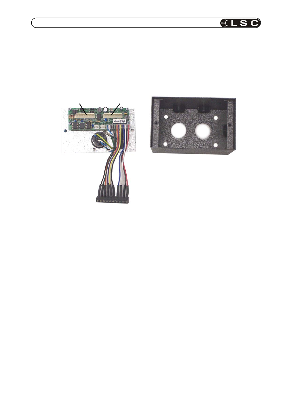
2.3 ISOPORT module
Each ISOPORT module is supplied inside a metal installation housing that contains internal
electronics which can be configured to suit individual installation requirements. The picture
below shows a disassembled ISOPORT series 1.
ISOPORT installation procedure.
1. Remove the two screws located on the front panel.
2. Separate the front panel and associated electronics from the installation housing (as
shown above).
3. Locate the installation housing in the desired location and secure it using the four mounting
holes located at the back of the housing. Four conduit ducting holes are provided in the
installation housing.
4. Configure
the
ISOPORT input to output relationships with jumper LK1 as shown in table 1
on page 5.
5. Configure
the
ISOPORT input terminations if required. Refer to figure 1 on page 5.
6. Connect the DMX512 data and power input wiring to the screw terminal wiring strip as
detailed in table 2 on page 6.
7. Replace the front panel electronics into the metal housing and secure with the two screws.
ISOport installation housing
ISOport front
Panel (series 1)
Screw terminal wiring strip
Isolation module
3 connector
Isolation module
2 connector