LSC Lighting ISOnode User Manual
Page 6
LSC Lighting Systems (Aust) Pty Ltd
Page 5
ISOseries Installation guide
Table 1 - ISOPORT Configuration options (ISOPORT series 2 and 3 only)
The ISOPORT allows various input to output relationships to be configured. These options are
configured by moving jumper LK1 on the isolation module to the desired position as shown in
the diagram below.
Input to output relationship
Isolation module 2
Isolation module 3
DMX A Input > Output 1
DMX B Input > Output 2
DMX C Input > Output 3
(ISOPORT series 3 only)
LK1 UP
LK1 UP
DMX A Input > Output 1
DMX A Input > Output 2
DMX A Input > Output 3
(ISOPORT series 3 only)
LK1 DOWN
LK1 DOWN
DMX A Input > Output 1
DMX A Input > Output 2
DMX C Input > Output 3
(ISOPORT series 3 only)
LK1 DOWN
LK1 UP
DMX A Input > Output 1
DMX B Input > Output 2
DMX A Input > Output 3
(ISOPORT series 3 only)
LK1 UP
LK1 DOWN
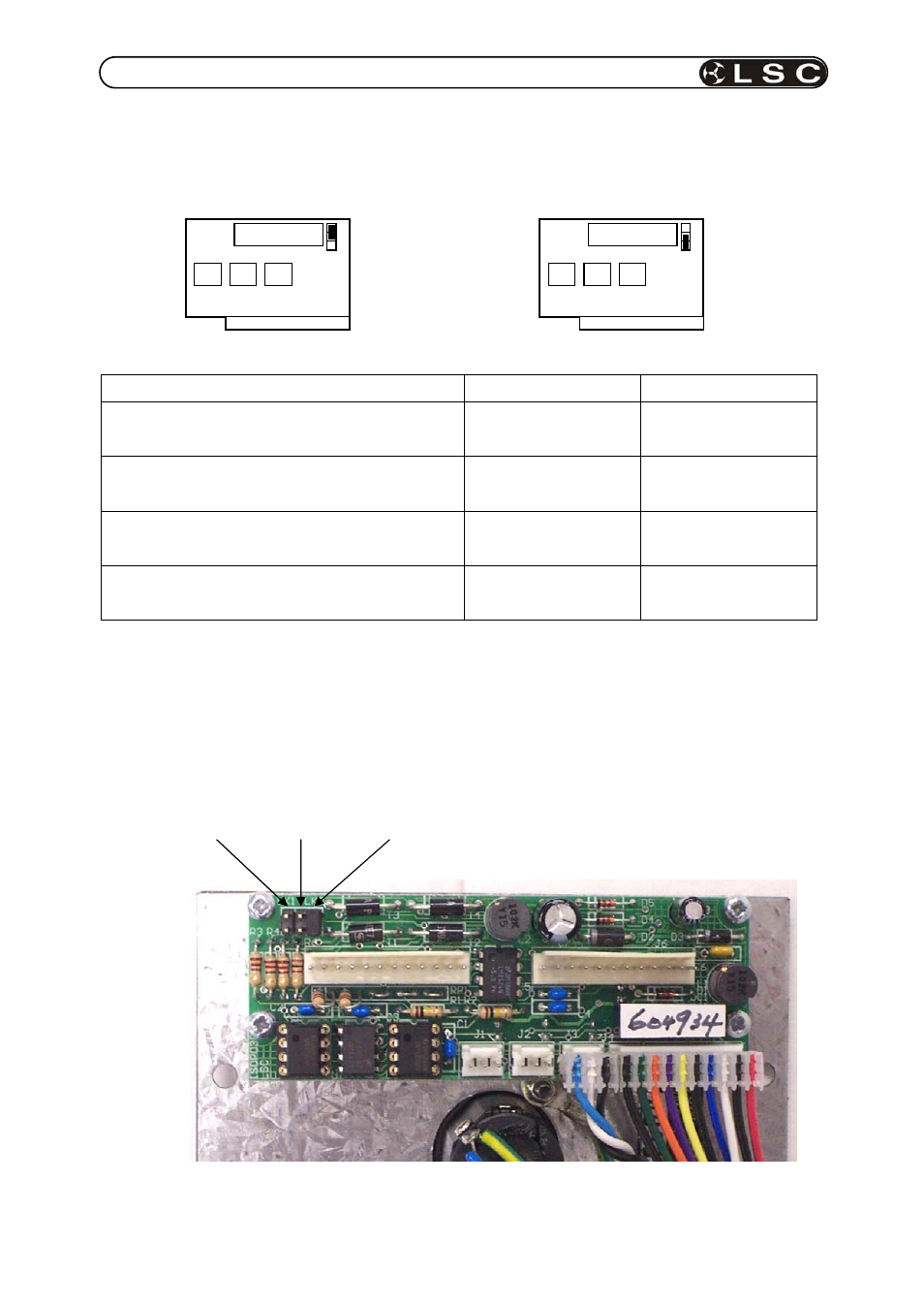
Figure 1 - ISOPORT DMX512 input termination.
The ISOPORT has integrated input termination resistors that can be used when the ISOPORT
is at the end of the DMX512 network and requires end of line termination. Each DMX512
input can be terminated by installing a jumper across the terminals shown below.
DMX C input DMX B input DMX A input (shown terminated)
Mating connector Mating connector
LK1
UP
LK1
DOWN